
Manual


Chapter 8 - RB-DMA2 Dual Digital Microphone Amplifier
8-4 Redbox User Handbook
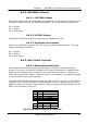
8.3.4. Input Level Indicators
For each input there is a tri-colour LED to give an indication of the level of the
incoming mic signals. Green indicates -18dBFS, orange indicates -12dBFS and red
indicates -6dBFS.
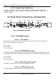
8.4. Rear Panel Connections and Operation
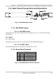
Fig 8-5: RB-DMA2 Rear Panel
8.4.1. RB-DMA2 Inputs
8.4.1.1. Mic Inputs
The XLR 3 pin sockets used for the microphone inputs are electronically balanced.
They have the following connections:
Pin 1: Screen
Pin 2: Phase
Pin 3: Non-phase
8.4.1.2. AES/EBU Sync Input
The digital AES/EBU synchronisation input XLR 3 pin socket has an impedance of 110
Ω and the signals meet the IEC 60968 specification. It has the following connections:
Pin 1: Screen
Pin 2: Phase
Pin 3: Non-phase
8.4.1.3. Word Clock Sync Input
The BNC TTL word clock input has an impedance of 50 Ω.
8.4.1.4. S/PDIF Sync Input
The S/PDIF digital phono input has an impedance of 75 Ω.
Disconnect the mains supply before removing the equipment covers.
This product must be earthedINPUT 1
WORD
CLOCK
S/PDIF INPUT
OUTPUT SELECT
STATUS
AES/EBU
INPUT
AES/EBU
OUTPUT
FREQUENCIES
AND SYNC MODES
AES/EBU
S/PDIF
INPUT 2
AES/EBU
S/PDIF
INPUT 2
LF FILTER
PHANTOM
POWER
INPUT 1 INPUT 2
INPUT 1
LF FILTER
OUTPUT 2OUTPUT 1
115V - 230V
8.4.3.3
8.4.1.1
8.4.2.3
8.4.3.4 8.4.2.2 8.4.1.3
8.4.3.5
8.4.3.1 & 8.4.3.28.4.1.
2
8.4.1.4
8.4.2.1