
Manual


Chapter 6 - RB-SC1 Sample Rate Converter
6-2 Redbox User Handbook
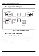
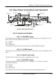
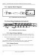
6.2. System Block Diagram
Fig 6-2: RB-SC1 System Block Diagram
6.3. Front Panel Indicators
6.3.1. Front Panel LED
The LED on the front panel is normally red to indicate that power is present on the
unit. However, it also has a secondary role to indicate the status of the digital inputs
Fast flashing between red and amber – indicates a loss of digital input signal.
Slow flashing between red and amber - when not in master mode this indicates the
absence of a synchronising input.
Digital
Input
Digital Sync
Input
AES/EBU
AES/EBU
SPDIF
SPDIF
Digital Source
Select
Digital Sync
Select
AES
Receiver
AES
Receiver
Sample
Rate
Converter
AES
Transmitter
Master
Clock
Generator
Frequency
Select
Clock
Conversion
Clock
Digital Send
Select
Word Clock
Digital
Output
AES/EBU
SPDIF