
Manual


Chapter 5 - RB-DAC1 Digital to Analogue Converter
5.4. Rear Panel Connections and Operation
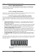
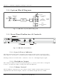
Fig 5-4: RB-DAC1 Rear Panel
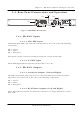
Disconnect the mains supply before removing the equipment covers.
This product must be eart hed
FULL SCALE
dB SETTINGS
ANALOGUE OUTPUTS
RIGHTLEFT
L
R
S/PDIF
INPUT
INPUT SELECT
AES/EBU
INPUT
AES/EBU
S/PDIF
5.4.2.1
5.4.2.2
5.4.3.1
5.4.1.1
5.4.3.3
5.4.1.2
5.4.3.2
5.4.1. RB-DAC1 Inputs
5.4.1.1. AES/EBU Input
The digital input XLR 3 pin socket has an impedance of 110 Ω. It has the following
connections:
Pin 1: Screen
Pin 2: Phase
Pin 3: Non-phase
The signals on this connector should meet the IEC 60968 specification
5.4.1.2. S/PDIF Input
The S/PDIF digital phono input has an impedance of 75 Ω.
5.4.2. RB-DAC1 Outputs
5.4.2.1. Analogue Outputs (Left and Right)
The XLR 3 pin output plug connectors are electronically balanced with an output
impedance of less than 50 Ω. They have the following connections:
Pin 1: Screen.
Pin 2: Phase.
Pin 3: Non-phase.
5.4.2.2. RCA Phono Outputs (Left and Right)
These RCA (phono) outputs are unbalanced and have an output impedance of less
than 75Ω.
Redbox User Handbook 5-3