
Manual


Chapter 5 - RB-DAC1 Digital to Analogue Converter
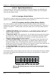
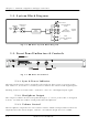
5.2. System Block Diagram
Fig 5-2: RB-DAC1 System Block Diagram
DAC
AES
Receiver
Digital Source
Selector
AES/EBU
S/PDIF
Stereo Headphone
Output
Volume Control
XLR
Professional
Balanced Output
Phono
Consumer Unbalanced
Output
Digital
Input
L
L
R
R
Analogue
Outputs
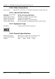
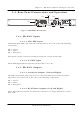
5.3. Front Panel Indicators & Controls
RB-DAC1
DIGITAL - ANALOG CONVERTER
HEADPHONE VOLUME
5.3.1
5.3.3
Fig 5-3: RB-DAC1 Front Panel
5.3.1. Sync & Power Indicator
The LED on the front panel is normally red to indicate that power is present on the
unit. However, it also has a secondary role to indicate the status of the digital inputs :
Flashing between red and amber – indicates a loss of a valid digital input signal.
5.3.2. Headphone Output
The output available on the front panel through a ¼” stereo jack socket, is designed
to drive 150 mW into 32Ω to 600Ω professional headphones.
5.3.3. Volume Control
The headphone output has its own volume control, which is independent of the level
adjustment for the main outputs, and has a maximum output level of +12dBu.
5-2 Redbox User Handbook