
Manual

Chapter 4 - RB-ADDA Combined A/D and D/A Converter
4-2 Redbox User Handbook
The analogue inputs have left and right level controls using pre-set potentiometers
and DIP switches allowing a signal range from +9dBu to +27dBu. The analogue
outputs have an output level control, allowing full-scale settings selectable from
+12dBu, +18dBu or +24dBu. There are factory-set internal level controls for the
analogue outputs allowing gain adjustment of ±1dB.
There are buttons to select either the AES/EBU or S/PDIF input or output for the D/A
and A/D sections respectively. The output bit depth can be selected from 16, 20 or
24 bits. Inputs of a different bit depth to the output are dithered using a
psychoacoustic noise filter.
For the digital output, there is a switch available to define the content of the channel
status bits embedded within the digital audio stream. The channel status bits will be
forced to Professional Mode for sample rates above 48kHz as they are not supported
by the Consumer Mode. For sample rates of 32kHz, 44.1kHz and 48kHz, the status
bits can be either set to Professional or Consumer Mode.
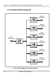
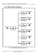
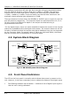
4.2. System Block Diagram
Fig 4-2: RB-ADDA System Block Diagram
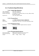
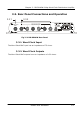
4.3. Front Panel Indicators
The LED on the front panel is normally red to indicate that power is present on the
unit. However, it also has a secondary role to indicate the status of the digital inputs
• Fast flashing between red and amber – indicates a loss of digital input signal or
that the unit is being calibrated.
Gain
Di
g
ital Send
Select
ADC
AES
Transmitter
Digital Source
Select
AES
Receiver
Frequency
Select
Master
Clock
Generator
Digital Input
AES/EBU
SPDIF
DAC
L
L
L
L
R
R
R
R
Consumer
Unbalanced
Digital Output
Analog Output
Consumer
Unbalanced
Professional
Balanced
Recovered
Clock
Professional
Balanced
Analog Input
Select
Analog Input
Gain
AES/EBU
SPDIF