
Handbook


Redbox User Handbook No 1
111
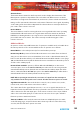
Front panel LED indicators by the MAIN and AUX buttons show individually left and right
programme and alarm conditions for both the main and auxiliary inputs.
A powerful feature of the RB-DSD1 is that by using the Sonifex SCi serial software, the unit
can be programmed for dierent delay durations, levels and switching functions so that you
can programme the unit for your specic application. A front panel DIPSwitch congures the
unit to be controlled serially and a front panel LED indicates serial operation. Contact Sonifex
for further information if you have a particular requirement that isn’t catered for by the
RB-DSD1 as standard.
The RB-DSD1 has been designed to have a passive signal path through the main input, so
if power to the unit fails, signal input 1 is routed to output 1 and signal input 2 is routed to
output 2. This is essential for applications such as installation at transmitter sites, where a
power failure to the unit should not prevent the audio input signal from being output to the
transmitter. Note: This applies to the AES/EBU & S/PDIF I/O, but not the TOSLink optical I/O.
Fig 10-2: RB-DSD1 System Block Diagram
S/PDIF
S/PDIF
Optical
AES
Optical
S/PDIF
Freq Select
AES Sync
Word Clock
Video Optional
Digital Source
Select
Digital Input 1
Digital Input 2
Clock
Select
Master
Clock
Generation
VID RX
AES RX
WC RX
AES
RX SRC
AES
Optical
S/PDIF
RX SRC
DSP
Digital Output 2
Digital Output 1
AES
Optical
TX
TX
Power
Failure
Relay
Power
Failure
Relay
Fig 10-3: RB-DSD1 Front Panel Controls and Indicators
Reset
Button
Duration
& Serial
Settings
Serial
LED
Level
Settings
Stereo/Mono
& Sync
Settings
MAIN
Button &
Indicators
AUX
Button &
Indicators
RESTORE
Button &
Indicator
SYNC
Button &
Indicators
Front Panel Controls and Indicators
The LED in the front panel is normally red to indicate power to the unit.
10
SYNCHRONISERS, DELAYS &
SILENCE DETECTORS
SYNCHRONISERS, DELAYS & SILENCE DETECTORS - RB-DSD1