
User guide

6
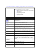
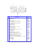
FUNCTIONS OF KEYS, CONTROLS, INDICATIONS, AND CONNECTORS
FRONT PANEL
LCD screen
Displays prompts and the following control parameters:
Amplitude selected
Output power delivered to the probe in watts, and as percentage
of the total power
Selected duration of processing
Actual processing time
Elapsed time
Set and read temperature
Pulse duration
0 – 9 key
Input digits.
CLEAR key
Clears preceding entry.
ENTER
REVIEW key
Enters data into the program, and selects various parameters, for display
on the LCD screen.
TIMER key
Used with the numeric keys to set the duration of ultrasonic application –
from 1 second to 9 hours, 59 minutes, 59 seconds.
TEMP key
Used with the numeric keys to set the high temperature limit – from 1?C to
99?C. Red indicator lights when the temperature limit has been reached.
PULSE key
Used with the numeric keys to set the pulse mode. The ON cycle and OFF
cycle can be set independently from .1 second to 9.9 seconds. Red
indicator lights when pulser is in the OFF portion of the cycle.
SAVE key Used with the numeric keys to assign a number to a program and store that
program in memory. Up to 10 programs (0-9) can be stored. Lit red
indicator signals that a program identification number must be entered.
RECALL key
Used with numeric keys to recall any of 10 stored programs. Lit red
indicator signals that a program identification number must be entered.
HOLD key
Suspends operation. Red indicator lights when the processing cycle is
interrupted.
TUNE key Activates the ultrasonics for tuning purposes. Red indicator lights when
the power supply is set for tuning. Tuning must be performed in air wit the
probe out of the sample. The power supply should be tuned every time a
new converter or probe is used and following 10 minutes of continuous
operation.
START/STOP key
Starts or stops the ultrasonics. In the STOP mode the red indicator goes
off.
ON/OFF power switch
(located below the control panel)
Switches the main power on or off.
TUNER
(located below the control panel)
Optimizes performance by matching the frequency of the power supply to
that of the converter / probe assembly
AMPLITUDE control
(located below the control panel)
Controls the amplitude of vibration at the probe tip.
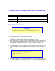
CAUTION
When using a microtip, never allow the amplitude to exceed 40%