USER’S GUIDE HIGH INTENSITY ULTRASONIC PROCESSOR Microprocessor Controlled 400-Watt Model 600-Watt Model TABLE OF CONTENTS Important Safeguards Specifications Low Surface Tension Liquids - Organic Solvents SECTION 1 – INSTALLATION Inspection Electrical Requirements Installing the Ultrasonic Processor SECTION II – OPERATION Principles of Ultrasonic Disruption Functions of Controls, Indications, and Connectors Preparations for Use Tuning Using the Ultrasonic Processor SECTION III – CALIBRATION Temperature Pro
IMPORTANT SAFEGUARDS READ BEFORE INSTALLING OR USING THE EQUIPMENT Your Ultrasonic Processor has been designed with safety in mind. However, no design can completely protect against improper usage, which may result in bodily injury and/or property damage. For your protection and equipment safeguard, observe the following warnings at all times, read the operating instructions carefully before operating the equipment, and retain this instruction manual for future reference.
SPECIFICATIONS POWER SUPPLY CONVERTER Dimensions……7 ½” x 13 ½” x 8 ½” (19 x 34 x 21.6 cm) Weight……………………………………….18 lbs (8 kg) Power (watts continuous)……………………400 and 600 Frequency………………………………………… 20 kHz Power Requirements…….. 100V, 117V or 220V 50/60Hz Monitor…………… Alpha-numeric liquid crystal display Power Control…… Continuous variable amplitude output Timer………………………………. 1 second to 10 hours Pulser…………………. On/Off-0.
ELECTRICAL REQUIREMENTS The Ultrasonic Processor requires a fused, single phrase 3-terminal grounding type electrical outlet capable of supplying 50/60 Hz at 100 volts, 115 volts, 220 volts, or 240 volts, depending on the voltage option selected. For power requirements, check the label on the back of the unit. WARNING For your personal safety, do not, under any circumstances, defeat the grounding feature of the power cord by removing the grounding prong.
SECTION II – OPERATION PRINCIPLES OF ULTRASONIC DISRUPTION The ultrasonic power supply converts 50/60 Hz line voltage to high frequency electrical energy. This high frequency electrical energy is transmitted to the piezoelectric transducer within the converter, where it is changed to mechanical vibrations. The vibrations from the converter are intensified by the probe, creating pressure waves in the liquid.
FUNCTIONS OF KEYS, CONTROLS, INDICATIONS, AND CONNECTORS FRONT PANEL LCD screen Displays prompts and the following control parameters: Amplitude selected Output power delivered to the probe in watts, and as percentage of the total power Selected duration of processing Actual processing time Elapsed time Set and read temperature Pulse duration 0 – 9 key Input digits. CLEAR key Clears preceding entry.
FUNCTIONS OF KEYS, CONTROLS, INDICATIONS, AND CONNECTORS (cont.) REAR PANEL Large Jack Connects to the footswitch cable. Small Jack Connects to the temperature probe. Connector Connects to the converter. Fuse(s) Protects against electrical overload Power Connector Connects to the electrical line cord. PREPARATION FOR USE CAUTION Do not operate an Ultrasonic Processor that has been in a very cold or hot environment for a prolonged period of time. Wait until it has reached room temperature 1.
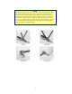
NOTE Should it become necessary to remove a probe, use the wrenches supplied. If the probe has been attached to the converter for a long period of time it might be necessary to use a vise. Be sure the vise has soft jaws or other means to prevent scratching. Secure the wide diameter portion of the probe in the jaws of the vise. Never grip the converter in the vise. Using a wrench, twist the converter off the probe. A tap of a hammer may be applied to the end of the wrench.
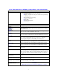
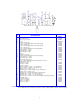
No 1 2 3 4 5 6 7 8 9 10 11 12 13 14 15 16 17 18 19 20 DESCRIPTION Converter Model CV26 Four element coupler Stepped top(s) 1 /8 ” (3mm) Booster Probe ½” (13mm) solid Probe ½” (13mm) with threaded end and replaceable tip Probe ¾” (19mm) solid Probe ¾” (19mm) with threaded end and replaceable tip Probe 1” (25mm) solid Probe 1” (25mm) with threaded end and replaceable tip Replaceable tip ½” (13mm) Replaceable tip ¾” (19mm) Replaceable tip 1” (25mm) Coupler Stepped tip 1/8” (3mm) Probe ½” (13mm) with thread
TUNING Tuning optimizes performance and insures maximum transfer of energy by matching the frequency of the power supply to that of converter/probe assembly. The power supply should be tuned 1) every time a new probe or accessory is used, 2) on occasions to compensate for the frequency variation caused by cavitation erosion 3) following 10 minutes of continuous operation and 4) when the sample temperature is significantly higher or lower than room temperature.
4. Press the TUNE key, and rotate the TUNER clockwise or counterclockwise until a minimum (not maximum) reading – usually less than 35 – is displayed on the POWER MONITOR bar graft. If a reading, of less than “35” cannot be obtained, the probe, cup horn, tip, microtip, extender or accessory is loose or out of resonance, or the power supply or converter require servicing. Note: Depressing the TUNE key energizes the ultrasonics for only 10 seconds. 1. 2. 3.
USING THE ULTRASONIC PROCESSOR The speed control on an automobile, can, to a certain extent, be compared to an Ultrasonic Processor. The speed control is designed to maintain the vehicles rate of travel constant. As the terrain changes, so do the power requirements. The speed control senses these requirements, and automatically adjusts the amount of power delivered by the engine in order to compensate for these ever changing conditions.
CAUTION Never allow liquid to spill into the converter. Do not use the cup horn without a splash shield Do not allow a microtip or extender to vibrate in air for more than 10 seconds. When working with a microtip never allow the AMPLITUDE control to be set above the microtip limit 40%. Ignoring these instructions will cause the microtip to fracture. Do not allow the vibrating microtip to contact anything but the sample.
5. If the function control parameters have been previously stored for a particular application, use the RECALL key to retrieve the control settings for that application. 6. To energize the ultrasonics, press the START key or the optional footswitch. To de-energize the ultrasonics, press the STOP key or release the footswitch. NOTE If the START key is pressed and the time limit has not been set, processing will remain uninterrupted until the STOP key is depressed.
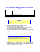
PROGRAM SET UP Set ON/OFF power switch to ON. The switch will illuminate and the screen will display the power rating of the Ultrasonic Processor, cautionary notices, and the following control parameters. TIME __:__:__ PULSE__:__:__ TEMP __ __?C AMPL __ __% AMPLITUDE: The amplitude is the only parameter that must be set in order for the Ultrasonic Processor to be operational. The other control parameters – Time and Pulse, do not have to be set for continuous operatio n. AMPL.
NOTE The probe is tuned to vibrate at a specific frequency. If the resonant frequency of the probe has changed, due to cavitation erosion or fracturing, a minimum reading will not be obtained. If an overload condition exits, or if minimum reading cannot be obtained (less than 20%) with the probe out of the sample, check the instrument without the prove to determine which component might be defective.
TEMPERATURE: The temperature function prevents overheating of the sample by continuously monitoring the sample temperature, and terminating the ultrasonics when the temperature reaches a predetermined setpoint. The ultrasonics is automatically reinstated when the temperature drops below the setpoint.
PULSE: By inhibiting heat build- up in the sample, the pulse function enables safe treatment of temperature sensitive samples at high intensity. In addition, pulsing enhances processing by allowing the material to settle back under the probe after each burst. The ON and OFF pulse duration can be set independently from .1 second to 9.9 seconds. During the OFF portion of the cycle, the red indicator on the PULSE key will illuminate.
SAVE: The save function retains in memory up to 10 control parameters under a storage identification (ID) number. To store the parameters under an ID number, (0-9) press the SAVE key. The indicator light on the SAVE key will illuminate and the screen will display. e.g. TIME 5:30:25 #__ PULSE On 2.5 TEMP 35? C AMPL 40 % Using the numeric keys, enter the ID number. e.g. TIME 5:30:25 # 7 PULSE On 2.
To retrieve from memory the parameters stored under that ID number, press the ENTER/REVIEW key. The screen will display: TIME 5:30:25 PULSE 2.5 : 1.0 TEMP 35? C AMPL 40 % NOTE To review all the information that has been stored, press keys 0 to 9 one at a time. IMPORTANT Proper care of the probe is essential for dependable operation. The intense cavitation will, after a prolonged period of time, cause the tip to erode, and the power output to decrease without showing up on the wattmeter.
SECTION III – CALIBRATION TEMPERATURE PROBE CALIBRATION Ultrasonic Processors shipped with the optional Temperature Probe have been calibrated as a set. If the Temperature Probe is acquired separately, calibration should be performed in accordance with the procedure outlined below. NOTE For optimum accuracy, the Temperature Probe and ultrasonic Processor should be calibrated as a set. To calibrate the Ultrasonic Processor, proceed as follows: 1. Fill a 500 ml vessel with approximately 50% ice and 50% water.
SECTION IV – SERVICE INFORMATION Your Ultrasonic Processor was designed to provide you with years of safe and dependable service. Nevertheless, because of component failure or improper usage, the possibility does exist that it might not perform as it should, shut down due to an overload condition or that it will stop working all together. The most probable causes for malfunction are listed below and should be investigated.
RETURN OF EQUIPMENT It is suggested that an Ultrasonic Processor in need of repair be sent back to the factory. In order to receive prompt service; always contact the factory before returning any instrument. Include date of purchase, model number and serial number. For instrume nts not covered by the warranty, a purchase order should be forwarded to avoid unnecessary delay. Care should be exercised to provide adequate packing to insure against possible damage in shipment.
SECTION V - OPERATING SUGGESTIONS AND TECHNIQUES DISRUPTING CELLS The disruption of cells is an important stage in the isolation and preparation of intracellular products. From research levels through to production, many areas of biotechnology, particularly recombinant technology, necessitate the use of ultrasonics for cell disruption. Although some biological products are secreted from the cell or released during autolysis, many others require sonication to release intracellular material.
Microorganisms differ greatly in their sensitivity to ultrasonic disintegration. For example, the most readily disintegrated are the rod- like forms (bacilli), while the spherical organisms (cocci) are much more resistant. The group Mycobacteria, to which the tuberculosis organism belongs, is particularly difficult to disrupt. Generally, animal cells are more easily disintegrated that plant cells, and red blood cells are more readily disintegrated than muscle cells because they lack a protective cell wall.
If enzymes cannot be used, the following procedures should be considered: Freezing the sample at -70?C overnight, then thawing it in water immediately prior to ultrasonic processing. Most animal tissues can be processed fresh (unfrozen). It is important to keep fresh tissue cold and to process it quickly (within 30 minutes) after dissection. When working with fresh tissue, the cells must be sonicated immediately at the time the GITC lysis solution is added.
zymolase, glucalase and / or lyticase to produce spheroplasts that are readily lysed may also be useful. To disrupt filamentous fungi, scrape the mycelial mat into a cold mortar, add liquid nitrogen and grind to a fine powder with a pestle. The powder can then be thoroughly sonicated in lysis buffer to solubilize completely. As fungi may also be rich in polysaccharides, pretreatment with polyvinylpyrrolidone (PVP) may be beneficial.
Various methods can be used to measure the efficiency of the disruption. For example, a visual count can be made using a microscope. For greater accuracy, a protein assay could be used. This procedure is widely recognized as a good method for measuring cell disruption by taking into account the amount of protein released after disruption. The disrupted cells are then tested and checked against this number for percentage breakage. There are several types of protein assays.
To inhibit sample loss in test tube due to sticking, siliconize the test tube as follows: Wash and dry the test tube thoroughly, coat with silicone, then air dry. “Sigmacote” manufactured by Sigma Chemical Co., 3050 Spruce Street, St. Louis, Missouri 63103, USA, phone (314) 771-5765, is ideally suited for that purpose. High viscosity and concentration are problematic. 2,000 cps and 15% concentration by weight are maximum limits.