
User guide

FUNCTIONS OF KEYS, CONTROLS, INDICATORS, AND CONNECTORS
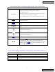
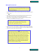
FRONT PANEL
LCD screen
Displays prompts and the following control parameters:
• Amplitude selected
•
Amount of output power delivered to the probe in watts, and as a
percentage of either 100 watts or 130 watts.
•
Accumulated amount of energy in Joules delivered to the probe.
CLEAR
key
Clears preceding entry.
ENTER
REVIEW
key
Used to enter the amplitude selected, and view amplitude, power, and
energy
START/STOP
key
Starts or stops the ultrasonics. In the STOP mode the red indicator goes
off.
key
Switches the main power on.
key
Switches the main power off.
AMPL
Controls the amplitude of vibration at the probe tip.
▲ ▼
key
Used with the AMPL key when the unit is on stand-by to set the amplitude
of vibration at the probe tip. Also used to increase or decrease the
amplitude in small increments while the unit is running. To accomplish
this task, depress the AMPL key to display Amplitude Setting, then
depress the ▲ or ▼ key as required.
FUNCTIONS OF KEYS, CONTROLS, INDICATORS, AND CONNECTORS (cont.)
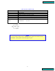
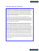
REAR PANEL
9 pin D-sub connector
Connects to external actuation device, and enable power and frequency
monitoring.
Footswitch jack Connects to the footswitch cable.
Coax connector Connects to the converter.
Power module Connects to the electrical line cord and encases the fuse(s).
O
|
7
Table of Contents
Table of Contents