Click for English Guides Summary USER’S GUIDE AUTOTUNE SERIES HIGH INTENSITY ULTRASONIC PROCESSOR WITH MANUAL PULSER MICROPROCESSOR CONTROLLED 100 Watt Model • 130 Watt Model TABLE OF CONTENTS Warranty Important Safeguards Low Surface Tension Liquids - Organic Solvents SECTION 1 – INSTALLATION Inspection Electrical Requirements Installing the Ultrasonic Processor SECTION II – OPERATION Principles of Ultrasonic Disruption Functions of Controls, Indicators, and Connectors Preparations for Use Using the Ultr
Table of Contents WARRANTY Your Ultrasonic Processor is warranted and backed by the manufacturer for a period of three years from the date of shipment against defects in material and workmanship under normal use as described in this instruction manual.
Table of Contents IMPORTANT SAFEGUARDS READ BEFORE INSTALLING OR USING THE EQUIPMENT Your Ultrasonic Processor has been designed with safety in mind. However, no design can completely protect against improper usage, which may result in bodily injury and/or property damage. For your protection and equipment safeguard, observe the following warnings at all times, read the operating instructions carefully before operating the equipment, and retain this instruction manual for future reference.
Table of Contents CAUTION LOW SURFACE TENSION LIQUIDS – ORGANIC SOLVENTS The probes (solid or with a replaceable tip) are tuned elements that resonate at a specific frequency. When using a ½” (13 mm) probe with a replaceable tip, if the replaceable tip is removed or isolated from the rest of the probe, the probe will no longer resonate at that frequency, and the power supply will fail.
Table of Contents ELECTRICAL REQUIREMENTS The Ultrasonic Processor requires a fused, single phrase 3-terminal grounding type electrical outlet capable of supplying 50/60 Hz at 100 volts, 115 volts, 220 volts, or 240 volts, depending on the voltage option selected. For power requirements, check the label on the back of the unit. Should it become necessary to convert the unit for different voltage operation, proceed as follows. 1. 2. 3. 4.
Table of Contents SECTION II – OPERATION PRINCIPLES OF ULTRASONIC DISRUPTION The ultrasonic power supply converts 50/60 Hz line voltage to high frequency electrical energy. This high frequency electrical energy is transmitted to the piezoelectric transducer within the converter, where it is changed to mechanical vibrations. The vibrations from the converter are intensified by the probe, creating pressure waves in the liquid.
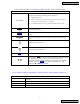
Table of Contents FUNCTIONS OF KEYS, CONTROLS, INDICATORS, AND CONNECTORS FRONT PANEL Displays prompts and the following control parameters: LCD screen • • • CLEAR key ENTER REVIEW key START/STOP key | Amplitude selected Amount of output power delivered to the probe in watts, and as a percentage of either 100 watts or 130 watts. Accumulated amount of energy in Joules delivered to the probe. Clears preceding entry.
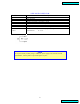
Table of Contents Pin No. 9-PIN D-SUB CONNECTOR Description 1 2 3 4 5 6 7 Not connected Not connected Not connected Enables connection to a frequency counter. Enables connection to an external power monitor (5 mv = 1 watt) Ground Energizes the ultrasonics when connected to ground. 8 and 9 Enables the intensity to be remotely adjusted using an external 10k potentiometer.
Table of Contents PREPARATION FOR USE CAUTION Do not operate an Ultrasonic Processor that has been in a very cold or hot environment for a prolonged period of time. Wait until it has reached room temperature. 1. Plug the electrical line cord into the electrical outlet, if the unit is already on; depress the O key. 2. If the optional footswitch is used, insert the plug into the jack located on the rear panel. Make sure that the plug is inserted forcefully all the way in. 3.
Table of Contents USING THE ULTRASONIC PROCESSOR The speed control on an automobile, can, to a certain extent, be compared to an Ultrasonic Processor. The speed control is designed to maintain the vehicles rate of travel constant. As the terrain elevations change, so do the power requirements. The speed control senses these requirements, and automatically adjusts the amount of power delivered by the engine in order to compensate for these ever changing conditions.
Table of Contents • • • • • • CAUTION Do not operate the power supply unless it is connected to the converter. Never allow liquid to spill into the converter. Do not use the cup horn without a splash shield Do not allow a microtip to vibrate in air for more than 10 seconds. Do not allow the vibrating microtip to contact anything but the sample. When working with samples containing solvents or low surface tension liquids, do not use a probe with a replaceable tip.
Table of Contents AMPLITUDE: Desired amplitude must be set in order for the Ultrasonic Processor to be operational. AMPL. displays the amplitude selected e.g. 40%. To set the amplitude at 40% when the ultrasonics is off, press the AMPL key and the ▲ or ▼ key for a 40% reading on the screen, and then press the ENTER/REVIEW key. The screen will display: Ampl 40 % The Ultrasonic Processor is now ready for continuous operation. To energize the ultrasonics, press the START key or the footswitch.
Table of Contents NOTE The probe is tuned to vibrate at a specific frequency. If the resonant frequency of the probe has changed, due to cavitation erosion or fracturing, a minimum reading will not be obtained. If an overload condition exits, or if minimum reading cannot be obtained (less than 20%) with the probe out of the sample, check the instrument without the probe to determine which component might be defective.
Table of Contents IMPORTANT Proper care of the probe is essential for dependable operation. The intense cavitation will, after a prolonged period of time, cause the tip to erode, and the power output to decrease without showing up on the wattmeter. The smoother and shinier the tip, the more power will be transmitted into the sample. Any erosion of the probe tip will increase the rate of future erosion.
Table of Contents SECTION III – SERVICE INFORMATION Your Ultrasonic Processor was designed to provide you with years of safe and dependable service. Nevertheless, because of component failure or improper usage, the possibility does exist that it might not perform as it should, shut down due to an overload condition or that it will stop working all together. The most probable causes for malfunction are listed below and should be investigated.
Table of Contents OVERLOAD CONDITION If the Ultrasonic Processor stops working, and an OVERLOAD indication is displayed on the screen, check for possible causes as outlined in the above paragraph, then press the key to switch the unit off, and the | O key to switch the unit back on. RETURN OF EQUIPMENT It is suggested that an Ultrasonic Processor in need of repair be sent back to the factory. In order to receive prompt service; always contact the factory before returning any instrument.
Table of Contents SECTION IV - OPERATING SUGGESTIONS AND TECHNIQUES DISRUPTING CELLS The disruption of cells is an important stage in the isolation and preparation of intracellular products. From research levels through to production, many areas of biotechnology, particularly recombinant technology, necessitate the use of ultrasonics for cell disruption.
Table of Contents Gram negative bacteria typically require 10 to 15 minutes of processing, while staphylococcus requires 20 to 30 minutes. Microorganisms differ greatly in their sensitivity to ultrasonic disintegration. For example, the most readily disintegrated are the rod-like forms (bacilli), while the spherical organisms (cocci) are much more resistant. The group Mycobacteria, to which the tuberculosis organism belongs, is particularly difficult to disrupt.
Table of Contents buffer. Collogenase may be used with collogen, lysostaphin with staphylococcus, and trypsin hyaluronidase with liver and kidney. If enzymes cannot be used, the following procedures should be considered: Freezing the sample at -70°C overnight, then thawing it in water immediately prior to ultrasonic processing. Most animal tissues can be processed fresh (unfrozen). It is important to keep fresh tissue cold and to process it quickly (within 30 minutes) after dissection.
Table of Contents Yeast can be extremely difficult to disrupt because their cell walls may form capsules or nearly indestructible spores. To process yeast, sonicate in a tube containing the sample, guanidinium-based lysis buffer and small glass beads (0.5 – 1 mm). Pretreatment with zymolase, glucalase and / or lyticase to produce spheroplasts that are readily lysed may also be useful.
Table of Contents for effective cellular disruption, it is not necessary that the vapor phase be oxygen or air since any gas except carbon dioxide will work just as well. Various methods can be used to measure the efficiency of the disruption. For example, a visual count can be made using a microscope. For greater accuracy, a protein assay could be used. This procedure is widely recognized as a good method for measuring cell disruption by taking into account the amount of protein released after disruption.
Table of Contents from previous use, clean the probe with a 20% Virkon solution and rinse with distilled water. For critical application, probes may be autoclaved. To inhibit sample loss in test tube due to sticking, siliconize the test tube as follows: Wash and dry the test tube thoroughly, coat with silicone, then air dry. “Sigmacote” manufactured by Sigma Chemical Co., 3050 Spruce Street, St. Louis, Missouri 63103, USA, phone (314) 771-5765, is ideally suited for that purpose.