USER’S GUIDE AUTOTUNE SERIES HIGH INTENSITY ULTRASONIC PROCESSOR MICROPROCESSOR CONTROLLED (SERIAL NO. "Y" OR HIGHER) 500 WATT MODEL • 750 WATT MODEL TABLE OF CONTENTS Warranty Important Safeguards Low Surface Tension Liquids – Organic Solvents SECTION I – INSTALLATION Inspection.......................................................................................1 Electrical Requirements ................................................................1 Installing the Ultrasonic Processor ..............
WARRANTY Your Ultrasonic Processor is warranted for a period of three years from the date of shipment against defects in material and workmanship under normal use as described in the instruction manual. During the warranty period, the manufacturer will, at its option, as the exclusive remedy, either repair or replace without charge for material and labor, the part(s) which prove to be defective, provided the unit is returned to us properly packed with all transportation charges prepaid.
IMPORTANT SAFEGUARDS READ BEFORE INSTALLING OR USING THE EQUIPMENT Your Ultrasonic Processor has been designed with safety in mind. However, no design can completely protect against improper usage, which may result in bodily injury and/or property damage. For your protection and equipment safeguard, observe the following warnings at all times, read the operating instructions carefully before operating the equipment, and retain this instruction manual for future reference.
SECTION I – INSTALLATION INSPECTION Prior to installing the Ultrasonic Processor, perform a visual inspection to detect any evidence of damage which might have occurred during shipment. Before disposing of any packaging material, check it carefully for small items. The equipment was thoroughly inspected and carefully packed before leaving our factory. The carrier, upon acceptance of the shipment, assumed responsibility for its safe delivery.
SECTION II – OPERATION PRINCIPLES OF ULTRASONIC DISRUPTION The ultrasonic power supply converts 50/60 Hz line voltage to high frequency electrical energy. This high frequency electrical energy is transmitted to the piezoelectric transducer within the converter, where it is changed to mechanical vibrations. The vibrations from the converter are intensified by the probe, creating pressure waves in the liquid.
FUNCTIONS OF KEYS, CONTROLS, INDICATORS, AND CONNECTORS FRONT PANEL Displays prompts and the following control parameters: • Amplitude selected • Output power delivered to the probe in watts, and as percentage of the total power Screen • Selected duration of processing • Actual processing time • Elapsed time • Set and read temperature • Pulse duration • Accumulated amount of energy in Joules delivered to the probe. 0 – 9 key CLEAR key Input digits. Clears preceding entry.
FUNCTIONS OF KEYS, CONTROLS, INDICATORS, AND CONNECTORS (cont.) REAR PANEL 9-pin D-sub connector Connects to external actuation device, and enable power and frequency monitoring Footswitch jack Connects to the footswitch cable. Coax connector Connects to the converter. Power module Connects to the electrical line cord and encases the fuse(s). Temperature probe jack Connects to the optional temperature probe. 9-PIN D-SUB CONNECTOR Pin No.
PREPARATION FOR USE CAUTION Do not operate an Ultrasonic Processor that has been in a very cold or hot environment for a prolonged period of time. Wait until it has reached room temperature 1. Plug the electrical line cord into the electrical outlet. If the unit is already on, switch the unit off by depressing the O key. 2. If the optional footswitch is used, insert the footswitch plug into the jack located on the rear panel. Make sure that the plug is inserted all the way in. 3.
6
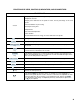
No 1 2 3 4 5 6 7 8 9 10 11 12 13 14 15 16 17 18 19 20 DESCRIPTION Converter Model CV33 Four element coupler Stepped top(s) 1/8” (3mm) Booster Probe ½” (13mm) solid Probe ½” (13mm) with threaded end and replaceable tip Probe ¾” (19mm) solid Probe ¾” (19mm) with threaded end and replaceable tip Probe 1” (25mm) solid Probe 1” (25mm) with threaded end and replaceable tip Replaceable tip ½” (13mm) Replaceable tip ¾” (19mm) Replaceable tip 1” (25mm) Coupler Stepped tip 1/8” (3mm) Probe ½” (13mm) with thread
USING THE ULTRASONIC PROCESSOR The speed control on an automobile, can, to a certain extent, be compared to an Ultrasonic Processor. The speed control is designed to maintain the vehicles rate of travel constant. As the terrain changes, so do the power requirements. The speed control senses these requirements, and automatically adjusts the amount of power delivered by the engine in order to compensate for these ever changing conditions.
CAUTION Do not operate the power supply unless it is connected to the converter. Press the I key. The screen will display the power rating and the frequency of the Ultrasonic Processor, and the following control parameters. TIME __:__:__ PULSE _ _ _ _ TEMP __ __°C AMPL __ __% AMPLITUDE: The amplitude is the only parameter that must be set in order for the Ultrasonic Processor to be operational. The other control parameters – Time and Pulse, do not have to be set for continuous operation. AMPL.
NOTE If the START key is pressed and the time limit has not been set, processing will remain uninterrupted until the STOP key is depressed. If the START key is pressed and the time limit has been set, processing will remain uninterrupted until the set time limit expires, or the STOP key is pressed – whichever occurs first. If a footswitch is use, and the time limit has not been set, processing will remain uninterrupted as long as the footswitch is depressed.
3. Depress the START key. CAUTION When working with a ¾" (19 mm) probe or extender, do not set the amplitude above 70. With a 1" (25 mm) probe, do not operate continuously with the amplitude set above 90. 4. Using the ▲ or ▼ keys, increase or decrease the amplitude as required. TIMER: In the pulsed mode the processing time will be different from the elapsed time because the processing time function monitors and controls only the ON portion of the duty cycle.
PULSER: By inhibiting heat build-up in the sample, the pulse function enables safe treatment of temperature sensitive samples at high intensity. In addition, pulsing enhances processing by allowing the material to settle back under the probe after each burst. The ON and OFF pulse duration can be set independently from 1 second to 59 seconds. During the OFF portion of the cycle, the red indicator on the PULSER key will illuminate.
REVIEW: The REVIEW function provides a “window” on the process by displaying various operating parameters without process interruption. Pressing the ENTER/REVIEW key repeatedly during processing will consecutively display the following information. a) Selected amplitude: e.g., Amplitude 40% b) Set processing time and elapsed processing time: e.g., Set 5:30:25 Time 0:57:03 c) Selected pulsing cycle, and actual pulsing cycle: e.g., Pulse 2.5 1.0/1.5 .
IMPORTANT Proper care of the probe is essential for dependable operation. The intense cavitation will, after a long period of time, cause the tip to erode, and the power output to decrease without showing up on the wattmeter. The smoother and shinier the tip, the more power will be transmitted into the sample. Any erosion of the probe tip will increase the rate of future erosion.
SECTION III – SERVICE INFORMATION Your Ultrasonic Processor was designed to provide you with years of safe and dependable service. Nevertheless, because of component failure or improper usage, the possibility does exist that it might not perform, as it should, shut down due to an overload condition or that it will stop working all together. The most probable causes for malfunction are listed below and should be investigated.
RETURN OF EQUIPMENT It is suggested that if a unit is in need of repair, it should be sent back to the factory. In order to receive prompt service; always contact the factory before returning any equipment. Include date of purchase, model number and serial number. For equipment not covered by the warranty, a purchase order should be forwarded to avoid unnecessary delay. Care should be exercised to provide adequate packing to insure against possible damage in shipment.
SONICS SAFETY CERTIFICATION FORM Items being returned: Please check only one item below: ___ The equipment was never used or exposed to any radiological, biological or chemical agents and is safe to handle, use or dispose of. ___ The equipment was used but not in conjunction with or exposed to any radiological, geological or chemical agents and is safe to handle, use, or dispose of.
SECTION IV OPERATING SUGGESTIONS AND TECHNIQUES DISRUPTING CELLS The disruption of cells is an important method in the field of proteomics and in the isolation and preparation of intracellular products. Isolation of subcellular fractions and concentration of proteins allow for more efficient identification and study of proteins of interest. From research levels through to production, many areas of biotechnology, particularly recombinant technology, necessitate the use of ultrasonics for cell disruption.
Single-cell organisms (micro-organisms) consist of a semipermeable, tough, rigid outer cell wall surrounding the protoplasmic membrane and cytoplasm. The cytoplasm is made up of nucleic acid, protein, carbohydrates, lipids, enzymes, inorganic ions, vitamins, pigments, inclusion bodies, and about 80% water. In order to isolate and extract any of these substances from inside the cell, it is necessary to break the cell wall and protoplasmic membrane.
The ability to control the amplitude at the probe tip is a prerequisite for process optimization. And because each application requires its own set of processing parameters, due to variation in volume and composition, the optimum amplitude can only be determined empirically. When processing a new sample, it is recommended that the amplitude be set first at 50% (30% with a microtip) and then increased of decreased as required.
the sample remains trapped in intact cells and, therefore, is unavailable for subsequent purification. For most samples, thorough disruption can be monitored by close inspection of lysate after disruption. There should be no visible particulates, except when disrupting materials containing hard, non-cellular components, such as connective tissue or bone. When processing difficult cells, pretreatment with an enzyme to “weaken” the cell walls is beneficial.
Detergent cell lysis is sometimes used in conjunction with ultrasonic processing to facilitate disruption. Detergents break the lipid barrier surrounding cells by solubilizing proteins and disrupting lipid:lipid, protein:protein and protein:lipid interactions. Detergents, like lipids, self-associate and bind to hydrophobic surfaces.
shown to effectively release recombinant proteins located in the cytoplasm of bacteria and is recommended when lysing mammalian cells. However, this method for lysis is not recommended when working with nitrilases as it has been noticed that purified nitrilases suffer structural damages upon freezing. Most animal tissues can be processed fresh (unfrozen). However, it is important to keep them cold and to process them quickly (within 30 minutes) after dissection.
When processing a sample with ultrasonics, always immerse the probe deep enough below the surface of the sample to inhibit aerosoling or foaming, foaming substantially reduces cavitation. Processing at a lower power setting without foam is much more effective than processing at a higher power setting with foam. Decreasing the power, increasing processing time and lowering the temperature of the sample will usually prevent aerosoling and foaming. Do not use any antifoaming agents or surfactants.
Before each application, place the tip in 100% ethanol and energize the power supply for a few seconds to remove any residual substances. If still concerned about contamination from previous use, clean the probe with a disinfectant such as 20% Virkon solution and rinse with distilled water. Probes are autoclavable. To inhibit sample loss in test tube due to sticking, siliconize the test tube as follows: Wash and dry the test tube thoroughly, coat with silicone, then air dry.
Fractional protein release, Rp, is calculated using the following equation and multiplying the result by 100: Rp = Cf – Cb Ct – Cb Cf = Free protein Ct = total protein Cb = Background protein This gives the actual disruption percentage, taking into account the background levels of protein before disruption.