Click for English Guides Summary USER’S GUIDE AUTOTUNE SERIES HIGH INTENSITY ULTRASONIC PROCESSOR 250 Watt Model • 500 Watt Model 600 Watt Model • 750 Watt Model TABLE OF CONTENTS Warranty Important Safeguards Low Surface Tension Liquids - Organic Solvents SECTION 1 – INSTALLATION Inspection Electrical Requirements Installing the Ultrasonic Processor SECTION II – OPERATION Principles of Ultrasonic Disruption Functions of Controls, Indications, and Connectors Preparations for Use Using the Ultrasonic Proces
WARRANTY Your Ultrasonic Processor is warranted and backed by the manufacturer for a period of three years from the date of shipment against defects in material and workmanship under normal use as described in this instruction manual.
IMPORTANT SAFEGUARDS READ BEFORE INSTALLING OR USING THE EQUIPMENT Your Ultrasonic Processor has been designed with safety in mind. However, no design can completely protect against improper usage, which may result in bodily injury and/or property damage. For your protection and equipment safeguard, observe the following warnings at all times, read the operating instructions carefully before operating the equipment, and retain this instruction manual for future reference.
CAUTION LOW SURFACE TENSION LIQUIDS – ORGANIC SOLVENTS The probes (solid or with a replaceable tip) are tuned elements that resonate at a specific frequency. If the replaceable tip is removed or isolated from the rest of the probe, the element will no longer resonate at that frequency, and the power supply will fail. Unlike aqueous (water based) solutions which rarely cause problems, solvents and low surface tension liquids are problematic.
ELECTRICAL REQUIREMENTS The Ultrasonic Processor requires a fused, single phrase 3-terminal grounding type electrical outlet capable of supplying 50/60 Hz at 100 volts, 115 volts, 220 volts, or 240 volts, depending on the voltage option selected. For power requirements, check the label on the back of the unit. WARNING For your personal safety, do not, under any circumstances, defeat the grounding feature of the power cord by removing the grounding prong.
SECTION II – OPERATION PRINCIPLES OF ULTRASONIC DISRUPSION The ultrasonic power supply converts 50/60 Hz line voltage to high frequency electrical energy. This high frequency electrical energy is transmitted to the piezoelectric transducer within the converter, where it is changed to mechanical vibrations. The vibrations from the converter are intensified by the probe, creating pressure waves in the liquid.
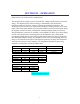
FUNCTIONS OF KEYS, CONTROLS, INDICATIONS, AND CONNECTORS FRONT PANEL LCD screen 0–9 key CLEAR key ENTER REVIEW key Displays prompts and the following control parameters: • Amplitude selected • Output power delivered to the probe in watts, and as percentage of the total power • Selected duration of processing • Actual processing time • Elapsed time • Set and read temperature • Pulse duration • Accumulated amount of energy in Joules delivered to the probe. Inputs digits. Clears preceding entry.
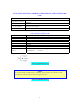
FUNCTIONS OF KEYS, CONTROLS, INDICATIONS, AND CONNECTORS (cont.) REAR PANEL Footswitch jack Connects to external actuation device, and enable power and frequency monitoring. Connects to the footswitch cable. Coax connector Connects to the converter. Power module Connects to the electrical line cord and encases the fuse(s). 9 pin D-sub connector 9-PIN D-SUB CONNECTOR Pin No. 1 2 3 4 5 6 7 Description Not connected Not connected Not connected Enables connection to a frequency counter.
PREPARATION FOR USE CAUTION Do not operate an Ultrasonic Processor that has been in a very cold or hot environment for a prolonged period of time. Wait until it has reached room temperature 1. Ensure that the AMPLITUDE dial is set fully counter-clockwise. 2. Plug the electrical line cord into the electrical outlet. 3. If the optional footswitch is used, insert the plug into the jack located on the rear panel. Make sure that the plug is inserted forcefully all the way in. 4.
Go To Top Of Document 10
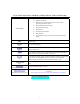
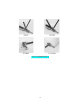
No 1 2 3 4 5 6 7 8 9 10 11 12 13 14 15 16 17 18 19 20 DESCRIPTION Converter Model CV33 Four element coupler Stepped top(s) 1/8” (3mm) Booster Probe ½” (13mm) solid Probe ½” (13mm) with threaded end and replaceable tip Probe ¾” (19mm) solid Probe ¾” (19mm) with threaded end and replaceable tip Probe 1” (25mm) solid Probe 1” (25mm) with threaded end and replaceable tip Replaceable tip ½” (13mm) Replaceable tip ¾” (19mm) Replaceable tip 1” (25mm) Coupler Stepped tip 1/8” (3mm) Probe ½” (13mm) with threaded
USING THE ULTRASONIC PROCESSOR The speed control on an automobile, can, to a certain extent, be compared to an Ultrasonic Processor. The speed control is designed to maintain the vehicles rate of travel constant. As the terrain changes, so do the power requirements. The speed control senses these requirements, and automatically adjusts the amount of power delivered by the engine in order to compensate for these ever changing conditions.
• • • • • CAUTION Never allow liquid to spill into the converter. Do not use the cup horn without a splash shield Do not allow a microtip or extender to vibrate in air for more than 10 seconds. When working with a microtip never allow the AMPLITUDE control to be set above the microtip limit 40%. Ignoring these instructions will cause the microtip to fracture. Do not allow the vibrating microtip to contact anything but the sample.
AMPLITUDE: The amplitude is the only parameter that must be set in order for the Ultrasonic Processor to be operational. The other control parameters – Time and Pulse, do not have to be set for continuous operation. AMPL. displays the percentage of maximum of amplitude e.g. 40%, set by the AMPLITUDE control. Rotate the AMPLITUDE control for a 40% reading on the screen – Ampl 40%.
NOTE The probe is tuned to vibrate at a specific frequency. If the resonant frequency of the probe has changed, due to cavitation erosion or fracturing, a minimum reading will not be obtained. If an overload condition exits, or if minimum reading cannot be obtained (less than 20%) with the probe out of the sample, check the instrument without the probe to determine which component might be defective.
PULSER: By inhibiting heat build-up in the sample, the pulse function enables safe treatment of temperature sensitive samples at high intensity. In addition, pulsing enhances processing by allowing the material to settle back under the probe after each burst. The ON and OFF pulse duration can be set independently from .1 second to 9.9 seconds. During the OFF portion of the cycle, the red indicator on the PULSER key will illuminate.
REVIEW: The REVIEW function provides a “window” on the process by displaying various operating parameters without process interruption. Pressing the ENTER/REVIEW key repeatedly during processing will consecutively display the following information. a) Selected amplitude: e.g. Amplitude Control 40% b) Set processing time and elapsed processing time: e.g. Set 5:30:25 Time 0:57:03 c) Selected pulsing cycle, and actual pulsing cycle: e.g. Pulse 2.5 1.0/1.5 .
SECTION III – SERVICE INFORMATION Your Ultrasonic Processor was designed to provide you with years of safe and dependable service. Nevertheless, because of component failure or improper usage, the possibility does exist that it might not perform as it should, shut down due to an overload condition or that it will stop working all together. The most probable causes for malfunction are listed below and should be investigated.
RETURN OF EQUIPMENT It is suggested that an Ultrasonic Processor in need of repair be sent back to the factory. In order to receive prompt service; always contact the factory before returning any instrument. Include date of purchase, model number and serial number. For instruments not covered by the warranty, a purchase order should be forwarded to avoid unnecessary delay. Care should be exercised to provide adequate packing to insure against possible damage in shipment.
SECTION IV - OPERATING SUGGESTIONS AND TECHNIQUES DISRUPTING CELLS Single-cell organisms (micro-organisms) consist of a semipermeable, tough, rigid outer cell wall surrounding the protoplasmic membrane and cytoplasm. The cytoplasm is made up of nucleic acid, protein, carbohydrates, lipids, enzymes, inorganic ions, vitamins, pigments, inclusion bodies, and about 80% water.
or Sigmund Lindner GmbH. P.O. Box 29. D-95483 Warmensteinach, Germany. Phone (49) 0 92 77 9 94 10, FAX (49) 0 92 77 9 94 99. When processing difficult cells, pretreatment with an enzyme such as lysozyme or byaluronidase might be beneficial. Glycosidase has been used successfully with yeast, lysostaphin with staphylococcus, collagenase with skin and cartilage, and trypsin hyaluronidase with liver and kidney.
moving cells circulate repeatedly below the probe. Solid materials however have a tendency to be repelled by the ultrasonic, and should be processed in a vessel large enough to accommodate the probe, yet small enough to restrict sample movement. For small samples, conical shaped test tubes are recommended. Although plastic tubes work well, glass and stainless steel tubes usually work better than plastic ones.
Go To Top Of Document 23