Click for English Guides Summary USER’S GUIDE AUTOTUNE SERIES HIGH INTENSITY ULTRASONIC PROCESSOR 70 Watt Model • 100 Watt Model 130 Watt Model • 150 Watt Model TABLE OF CONTENTS Warranty Important Safeguards Low Surface Tension Liquids - Organic Solvents SECTION 1 – INSTALLATION Inspection Electrical Requirements Installing the Ultrasonic Processor SECTION II – OPERATION Principles of Ultrasonic Disruption Functions of Controls, Indications, and Connectors Preparations for Use Using the Ultrasonic Process
WARRANTY Your Ultrasonic Processor is warranted and backed by the manufacturer for a period of three years from the date of shipment against defects in material and workmanship under normal use as described in this instruction manual.
IMPORTANT SAFEGUARDS READ BEFORE INSTALLING OR USING THE EQUIPMENT Your Ultrasonic Processor has been designed with safety in mind. However, no design can completely protect against improper usage, which may result in bodily injury and/or equipment damage. Please observe the following warnings at all times, read the operating instructions carefully before operating the equipment, and retain this instruction manual for future reference.
CAUTION LOW SURFACE TENSION LIQUIDS – ORGANIC SOLVENTS The probes (solid or with a replaceable tip) are tuned elements that resonate at a specific frequency. When working with the ½” (13mm) probe with replaceable tip, if the replaceable tip is removed or isolated from the rest of the probe, the probe will no longer resonate at the desired frequency, and the power supply will fail. Unlike aqueous (water based) solutions which rarely cause problems, solvents and low surface tension liquids are problematic.
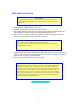
ELECTRICAL REQUIREMENTS The Ultrasonic Processor requires a fused, single phrase 3-terminal grounding type electrical outlet capable of supplying 50/ 60 Hz at 100 volts, 115 volts, 220 volts, or 240 volts, depending on the voltage option selected. For power requirements, check the label on the back of the unit. Should it become necessary to convert the unit for different voltage operation, proceed as follows. 1. 2. 3. 4. Ensure that the power cord is not connected to the electrical outlet.
SECTION II – OPERATION PRINCIPLES OF ULTRASONIC DISRUPSION The ultrasonic power supply converts 50/60 Hz line voltage to high frequency electrical energy. This high frequency electrical energy is transmitted to the piezoelectric transducer within the converter, where it is changed to mechanical vibrations. The vibrations from the converter are intensified by the probe, creating pressure waves in the liquid.
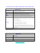
FUNCTIONS OF CONTROLS, INDICATORS, AND CONNECTORS FRONT PANEL AMPITUDE control When depressed, switches the main power on or off. When rotated, controls the amplitude of vibrations at the probe tip. PULSING button* Located on the converter. When depressed activates the ultrasonic. PULSE/CONTINUOUS switch* Select the application of ultrasonics as pulse or continuous. TIMER** Sets the duration of ultrasonic application from 1 minute to 10 minutes.
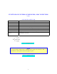
FUNCTIONS OF CONTROLS, INDICATORS, AND CONNECTORS (cont.) 9-PIN D-SUB CONNECTOR Pin No. Description 1 Not connected 2 3 4 Not connected Not connected Enables connection to a frequency counter. 5 Enables connection to an external power monitor (10 mv = 1 watt) 6 7 Ground Energizes the ultrasonics when connected to ground. 8 and 9 Enables the intensity to be remotely adjusted using an external 10k potentiometer.
PREPARATION FOR USE CAUTION Do not operate an Ultrasonic Processor that has been in a very cold or hot environment for a prolonged period of time. Wait until it has reached room temperature 1. Ensure that the AMPLITUDE is set to OFF. 2. Plug the electrical line cord into the electrical outlet. 3. If the optional footswitch is used, insert the plug into the jack located on the rear panel. Make sure that the plug is inserted forcefully all the way in. 4.
USING THE ULTRASONIC PROCESSOR The speed control on an automobile, can, to a certain extent, be compared to an Ultrasonic Processor. The speed control is designed to maintain the vehicles rate of travel constant. As the terrain changes, so do the power requirements. The speed control senses these requirements, and automatically adjusts the amount of power delivered by the engine in order to compensate for these ever changing conditions.
• • • CAUTION Do not operate the power supply unless it is connected to the converter. Never allow a microtip to vibrate in air for more than 10 seconds. Do not allow the vibrating probe to come in contact with anything but the sample. 1. Immerse the probe into the sample. 2. For continuous operation with units equipped with a pulsing button, set the PULSE / CONTINUOUS switch to CONTINUOUS. For pulsed operation, set the PULSE / CONTINUOUS switch to PULSE. Then set the AMPLITUDE control to 40. 3.
OPERATING SUGGESTIONS AND TECHNIQUES DISRUPTING CELLS Single-cell organisms (micro-organisms) consist of a semipermeable, tough, rigid outer cell wall surrounding the protoplasmic membrane and cytoplasm. The cytoplasm is made up of nucleic acid, protein, carbohydrates, lipids, enzymes, inorganic ions, vitamins, pigments, inclusion bodies, and about 80% water. In order to isolate and extract any of these substances from inside the cell, it is necessary to break the cell wall and protoplasmic membrane.
or Sigmund Lindner GmbH. P.O. Box 29. D-95483 Warmensteinach, Germany. Phone (49) 0 92 77 9 94 10, FAX (49) 0 92 77 9 94 99. When processing difficult cells, pretreatment with an enzyme such as lysozyme or byaluronidase might be beneficial. Glycosidase has been used successfully with yeast, lysostaphin with staphylococcus, collagenase with skin and cartilage, and trypsin hyaluronidase with liver and kidney.
moving cells circulate repeatedly below the probe. Solid materials however have a tendency to be repelled by the ultrasonic, and should be processed in a vessel large enough to accommodate the probe, yet small enough to restrict sample movement. For small samples, conical shaped test tubes are recommended. Although plastic tubes work well, glass and stainless steel tubes usually work better than plastic ones.
SECTION III – SERVICE INFORMATION Your Ultrasonic Processor was designed to provide you with years of safe and dependable service. Nevertheless, because of component failure or improper usage, the possibility does exist that it might not perform as it should, or that it will stop working all together. The most probable causes for malfunction are listed below and should be investigated. The unit was plugged into an electrical outlet that provides a different voltage from that required.
OVERLOAD CONDITION If the Ultrasonic Processor stops working, and OVERLOAD is displayed on the screen, check for possible causes as outlined in the above paragraph, then set the power switch to OFF then back to ON to reset the instrument. If the overload condition still exists, contact the Service Department. RETURN OF EQUIPMENT It is suggested that an Ultrasonic Processor in need of repair be sent back to the factory.