
Manual

• • • • • • • • • • • • • • • • • • • • • • • • • • • • • • • • • • • • • • • • • • • • • • • • • • • • • • • • • • • • • • • • • • • • • • • • • • • • • • • • • • • • • • • • • • • • • • • • • • • • • • • • • • • •
I N S T R U C T I O N M A N U A L • M O D E L G X L P O W E R S U P P LY
48
ANGULAR
DECIMAL
3 34 34 44 3
J5-13
J5-16
+VDC
+/- 1/2 DEG.
+/- 1/64
FRACTIONAL
.XXX= +/-0.005
.X= +/-0.030
.XX= +/-0.015
(EXCEPT AS NOTED)
TOLERANCES
1
2
1
CONDITIONS SPECIFIED HEREIN.
MATERIAL
CHK'D
DRAWN BY
DATE
SCALE
NEWTOWN, CT 06470
J5-2
J5-1
J5-17
J5-15
J5-14
RETURN
50 ma maximum
Digital Input 3
(Job Bit 2)
Digital Input 2
(Job Bit 1)
Digital Input 1
(Job Bit 0)
2
1
2
2
1
WPS
10-12-05
E-3171
53 CHURCH HILL RD.
DRAWING NO.
Digital Input 4
(Job Bit 3)
Isolated Supply #1
+V_loop_return
(30 VDC max)
CONFIDENCE, AND SHALL NOT BE DISCLOSED, USED OR DUPLICATED FOR ANY PURPOSE
WHATSOEVER WITHOUT THE PRIOR WRITTEN PERMISSION OF SONICS & MATERIALS INC.,
NEWTOWN, CT. THIS LEGEND SHALL BE MARKED ON ANY REPRODUCTIONS HEREOF IN WHOLE OR
CONFIDENTIAL INFORMATION
+24 Unreg
+24 VDC Unregulated
Ext +V_loop
THE INFORMATION AND DATA CONTAI NED HEREIN IS PROPRIETARY AND IS SUBMITTED IN
IN PA R T. RECEIPT OF THIS DOCUMENT SHALL BE DEEMED TO BE AN ACCEPTA NCE OF THE
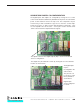
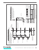
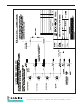
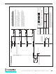
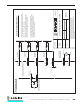
PLC OUTPUT TO SOURCE INPUT DIAGRAM
Source Inputs are the default configuration as shipped from
the factory. They may be switched to "Sink" if desired. See
Section x.xx, "Source/Sink Digital I/O Configuration"
G series Digital Inputs(DI)
J5 Mating Connector - AMP # 206437-1
Connector Pins - AMP # 66506-9
An external loop supply is required to power the input
circuit (normally provided by the PLC system). Alternatively,
2 isolated, unregulated, 24 VDC supplies are available on
the GX supply (J5 connector). These supplies are NOT
regulated and only rated for 50 ma total.
The GX digital inputs are optically isolated from the internal
circuits. An internal 2.4 K limiting resistor is provided for each
optical input. Do NOT apply AC voltage!
Contact Closure or transistor
to the loop supply. Typ 4 plcs.
PLC Output Card
PLC_DIGITAL_OUT
SUPPLY
Go To Top Of Document