Model GXL Power Supply I N S T R U C T I O N M A N U A L Sonics & Materials, Inc.
WARNING SAFETY PRECAUTIONS READ BEFORE INSTALLING OR USING THE EQUIPMENT This system has been designed to assure maximum operator safety. However, no design can completely protect against improper usage. For maximum safety and equipment protection, observe the following warnings at all times and read the instruction manual carefully before you attempt to operate the equipment. – High voltage is present in the equipment. Disconnect plug before removing cover or servicing.
TABLE OF CONTENTS IMPORTANT SERVICE LITERATURE . . . . . . . . . . . . . . . . . . . . . . . . . . . .4 Manual Change Information . . . . . . . . . . . . . . . . . . . . . . . . . . . . . .4 UNPACKING AND INSPECTION . . . . . . . . . . . . . . . . . . . . . . . . . . . . . . . .5 Visible Loss or Damage . . . . . . . . . . . . . . . . . . . . . . . . . . . . . . . . .5 Concealed Loss or Damage . . . . . . . . . . . . . . . . . . . . . . . . . . . . . .5 INTRODUCTION . . . . . . . . . . . . . . . . . . . . .
AUTOMATION INTERFACE & I/O CONTROLS . . . . . . . . . . . . . . . . . . . .31 External Job Address Lines . . . . . . . . . . . . . . . . . . . . . . . . . . . . .33 MAINTENANCE . . . . . . . . . . . . . . . . . . . . . . . . . . . . . . . . . . . . . . . . . . . . .34 General . . . . . . . . . . . . . . . . . . . . . . . . . . . . . . . . . . . . . . . . . . . . .34 Repairs / Service . . . . . . . . . . . . . . . . . . . . . . . . . . . . . . . . . . . . . .34 WARRANTY . . . . . . . . . . . . . . . . . . .
IMPORTANT SERVICE LITERATURE The system supplied with this instruction manual is constructed of the finest material and the workmanship meets the highest manufacturing standards. It has been thoroughly tested and inspected before leaving the factory and when used in accordance with the procedures outlined in this manual, will provide you with many years of safe and dependable service. NOTE: Please read carefully before operating the equipment, then forward to your service department.
UNPACKING AND INSPECTION NOTE: We recommend keeping all carton(s) and packing material in case it might be necessary to move the equipment, or to ship it for repair. Before unpacking the equipment, check the shipping carton for any visible damage. If you see any, be sure to follow the procedures described below under “Visible Loss or Damage.” Otherwise, proceed to remove the equipment from the carton. Before storing any packing material, check it carefully for small parts.
INTRODUCTION The GXL power supply is an ultrasonic generator with automatic frequency tuning and a built-in Microprocessor that features time, energy and distance controls. The Microprocessor is programmed with a multi-function keypad and information is displayed on the back-lit liquid crystal display (LCD). This power supply can be used with a pneumatic press or actuator, or with a stand-alone converter. (Note: Distance controls are not available with a stand-alone converter.
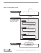
SONICS ULTRASONIC ASSEMBLY SYSTEMS 50/60 Hz Electrical power Power Supply/Generator Generates ultrasonic electrical energy (15/20/40 kHz) Ultrasonic electrical energy Actuator/Press Provides compressive force and mounting for Converter, Booster, Horn assembly Converter Transforms ultrasonic electrical energy to ultrasonic mechanical vibrations Ultrasonic Vibrations Booster Increases or decreases amplitude Ultrasonic Vibrations Horn Contacts and transfers vibrational energy to plastic part Ultrasonic Vib
GLOSSARY OF ULTRASONIC TERMS POWER SUPPLY/GENERATOR – The solid state power supply converts standard 50/60 Hz electrical energy to 15,000 Hz, 20,000 Hz or 40,000 Hz (15/20/40 kHz) electrical energy. ACTUATOR/WELDING PRESS – The pneumatic actuator provides compressive force and mounting for the converter, booster and horn assembly. The tabletop press consists of a base assembly, column and actuator (head).
INSTALLATION ELECTRICAL POWER REQUIREMENTS The power supply requires a fused, single-phase, standard 3-terminal grounding type receptacle capable of supplying the requisite voltage and current. Refer to the table below for power specification. The line cord of the controller/power supply is equipped with a 3-prong, grounding plug. Do not, under any circumstances, remove the ground prong. The plug must be plugged into a mating 3-prong, grounding type outlet.
ELECTRICAL CONNECTIONS The standard cable supplied with a Sonics press is 10 feet. Optional extension cables are available up to 15 feet without modification. NOTE: Do not plug the power supply into an electrical outlet until all other connections have been made. When making the initial electrical connections, make sure the power is disconnected and follow these precautions. 1. Do not strain or kink the cables. When going around corners, allow as wide a bend as possible.
CABLE CONNECTIONS – For Models with 700 to 2200 Watts Power: Located at the rear of the power supply are the cable connections as illustrated below. (The interconnecting cables will be supplied with your system.) NOTE: Detailed wiring diagrams are supplied in the Appendix at the back of this manual. ❶ J1, a round, 12-pin RF cable that connects the welding press or converter to the power supply.
CABLE CONNECTIONS – For Models with 3000 or 4000 Watts Power: Located at the rear of the power supply are the cable connections as illustrated below. (The interconnecting cables will be supplied with your system.) NOTE: Detailed wiring diagrams are supplied in the Appendix at the back of this manual. ❶ J1, a round, 12-pin RF cable that connects the welding press or converter to the power supply.
AVAILABLE CONVERTERS Item No.
OPERATING PROCEDURES FRONT PANEL CONTROLS AND INDICATORS Located on the front panel of the power supply are the following controls and indicators: 1. ON/OFF keys which turn the unit on and off. 2. LCD SCREEN which displays various settings, parameters and prompts as detailed in the following pages. In addition, during the weld process it displays a load meter indicator showing the power level of ultrasonics that is being delivered to the welding press (see #3 below). 3.
5. DISTANCE key which allows selection and display of distance settings and permits adjustment of the following distance parameters in .001 inch increments (from 0.000 to 9.999 inches, or 0.000 to 253.975 millimeters): a. Distance Incremental b. Distance Absolute c. Distance Limit Low d. Distance Limit High e. Pre-weld Limit Low f. Pre-weld Limit High g. Pre-Trigger Distance For a complete explanation of these parameters, refer to page 21. 6.
9. RECALL/SAVE key which allows up to 15 different jobs to be stored (saved) and recalled or changed upon demand. 10. ARROW keys (Up/Down) which allow scrolling through some menus and also serve as a toggle for displayed parameter options in some menus. 11. TEST key which can be used to test ultrasonic operation and displays idle losses of converter/booster/horn as a percentage of maximum power when key is depressed. Also functions as a frequency display. 12. O.L.
OPERATIONAL FEATURES – Adjustable Afterburst Timer to separate parts from horn. – Adjustable tolerance limits in energy (Ws), time (sec) and/or distance (inches or millimeters) with visual alarms. – Information displays including: number of assemblies, number of rejects, and number of cycles. – Fault displays. – Keypad security. – Self-diagnostic input test. – Storage capabilities of up to 15 jobs. – Deactivation of Calibration Pulse (i.e., when utilizing vacuum horns).
INITIAL OPERATION After the power supply is turned on (as described on previous page), follow these steps: 1. Make sure that all necessary preparations have been made with regard to the ultrasonic system and tooling, and that the items to be welded are in position. 2. Press and hold the TEST button. While depressing the TEST button, check the LCD display.
The Alarm screen displays information about the alarm(s) that have been triggered by the system encountering parameters outside of the specified tolerance limits. The screen will indicate whether alarms occurred in Time, Distance or Energy. If there are no alarms, dashes will display. If there are alarms, an L (for Low limit, indicating that the low limit was violated) and/or an H (for High limit, indicating that the high limit was violated) will display by the applicable mode (time, distance or energy).
will display “02.00 sec,” with the “sec” flashing, along with whatever energy was delivered. The peak power delivered (%Pmax) will be displayed as a percent of the supply rating. The ability to specify Time, Energy and Distance affords maximum control of the weld process. However, when entering your specifications in the various menus described below, keep in mind that the settings from previous use remain in effect until you make a change and use the Enter key to register a new value.
DISTANCE SETTINGS There are 7 distance parameters that can be specified. To better understand the distance parameters and corresponding terms used, please see the diagram below and note the following definitions. HEAD UP/ INITIAL TRAVEL HORN CONTACT WELD HORN HORN 1 2 4L 5L 3 TA PAR TB PAR TA PAR TB PAR 4H 6 D LDE WE T R A P 5H ➀ Home Position: when the converter head assembly is in the full up position, not in contact with the parts to be welded.
if too many parts have been installed. If the pre-weld window is violated, the system will abort the cycle. ➄ Post-Weld Window: If the parts are found within the pre-weld window, the weld portion of the cycle will begin. Note the “squiggle” line representing that the parts are now welded together. The weld has been completed by achieving one of the control set points – time, distance or energy. The Hold time has completed and the mechanical assembly is just about to retract away from the parts.
cycle and examined against a post-weld window (as explained in item 5 above), the lower limit of which is defined by this value. If the final travel distance is less than this entry, a distance low alarm will be indicated on the Alarm Screen display and by a flashing LED on the distance key. NOTE: The distance limit low/high is entered as an absolute number if the absolute distance set point has been programmed.
Press the Energy key again (and successively after each menu display) to advance to these next screen displays. Energy Limit Low – sets the low energy alarm examination point (as a process control tolerance limit). An energy alarm will be triggered if the actual weld energy is less than this value. By specifying values for this limit and the Energy Limit High, a weld energy “window” can be created in which a ”good weld” can occur.
TRIGGER Selection of the trigger mode is achieved by pressing the Trigger Key and then using the Up/Down arrow keys as a toggle to select one of the following modes to act as the trigger to start ultrasonics. Delay Timer – selecting this mode means that the ultrasonics will be triggered when the Delay Time specified in the Time menu is reached.
ADDITIONAL FEATURES AND FUNCTIONS JOB STORAGE Up to 15 different jobs may be stored and recalled or changed upon demand. Typical job parameters stored include Time, Energy, Force Trigger Setting, Time and Energy Limits, Amplitude, and Cal Pulse ON/OFF. Save To use the job storage feature, press the Recall/Save key. If the “recall” option is displayed on the screen press the button again. The Save display appears as follow: Save to Job # —— Saved jobs will be numbered 01 through 15.
FREQUENCY DISPLAY The TEST key can also be used to display the running frequency. When the press head is in the UP position, press and hold the TEST key for 3 seconds. The information on the display will change from the power display (watts) to a frequency counter display (Hz). After this switch, the power is captured (no longer updated) and the frequency display will update every second. This information can help diagnose problems with the horn and/or stack assembly.
KEYPAD SECURITY The keypad can be “locked,” so that no new parameters or commands can be entered via the keyboard, thereby preventing unauthorized cancellation or adjustment. To activate the security feature, press and hold the numeral 7 key on power up.
PRINT LINE OUTPUT NOTE: The Print Line option default is “OFF.” Switch 5 determines OFF/ON (see page 52). At the end of every weld cycle, the power supply sends an ASCII print line which includes the data for weld time, distance, energy, maximum power and alarm status. This line can be directed to a printer, a PLC ASCII card or a computer running any terminal program that will present the information. (The hyperterminal program is included with any PC under the Accessories/Communications directory.
From left to right, the data items show the following information: (for more detailed information on these items and the print output, refer to the Appendix) Position 1 = Customer Resettable Counter (CRC) Position 2 = Actual weld time Position 3 = Distance data (applicable for Model GXL only) Position 4 = Energy data (applicable for Models GXL or GXE only) Position 5 = Maximum percent power number Position 6 = Any alarm violations for time (T), distance (D) or energy (E) Position 7 = The last job number sav
AUTOMATION INTERFACE & I/O CONTROLS As listed below, there are several interface signals available for operating the power supply via external digital control lines. These lines are used to initiate a weld cycle and to monitor the operation (see External I/O Connection drawing E-3164 in the Appendix). 1. Impulse Input – the impulse input signal is used to initiate a weld cycle by external contact to ground. The contact must be closed for a minimum of 50 milliseconds for the welder to recognize the command.
signal to qualify these outputs, if ready is true, then the Good Part / Bad Part outputs are valid. 4. DO4 – There is one extra digital output that is reserved for future application. 5. DI1, DI2, DI3 and DI4 – Four digital input signals are used for setting an external job selection when the keyboard is “Locked.” 15 sets of weld control parameters may be stored in the controller’s battery RAM area. (see page 26, Job Storage).
EXTERNAL JOB ADDRESS LINES 0= OFF or open line 1= ON or contact closed DI1 0 1 0 1 0 1 0 1 0 1 0 1 0 1 0 1 DI2 0 0 1 1 0 0 1 1 0 0 1 1 0 0 1 1 DI3 0 0 0 0 1 1 1 1 0 0 0 0 1 1 1 1 DI4 0 0 0 0 0 0 0 0 1 1 1 1 1 1 1 1 JOB# No job change 1 2 3 4 5 6 7 8 9 10 11 12 13 14 15 Note that job Code 0 (0, 0, 0, 0) is not a valid job code and does not cause a job recall operation. Ex: If the last job recalled was Job 10 and the inputs are set to code 0, then Job 10 still dictates the active job settings.
MAINTENANCE GENERAL 1. Always make sure the power supply has adequate ventilation by keeping sufficient space around the assembly. 2. Periodically check the ventilation grilles and clean as necessary. REPAIRS / SERVICE If problems are encountered, contact our Service Department at 1-800-7451105. It is suggested that a system in need of repair be sent back to the factory with a written description pertaining to the nature of the problem.
WARRANTY Sonics & Materials, Inc., hereinafter referred to as "Sonics", warrants its products for a period of one year from the date of original shipment against defects in materials and workmanship under normal installation, use and maintenance as described in the operating instructions which accompany such equipment.
For components and parts not manufactured by Sonics but included in Sonics manufactured equipment, this warranty shall be limited to the warranty as given to Sonics by said original component or part manufacturer. Ultrasonic horns supplied by Sonics are manufactured to exacting specifications and are tuned to vibrate at a specific frequency. Using an out-of-tune horn will cause damage to the equipment and may result in warranty nullification.
APPENDIX PRINT LINE OUTPUT DATA ITEMS NOTE: Refer to page 29 for additional Print Line Output. Item 1: Using the first line of the sample listing above, item 1 is the “Customer Resettable Counter” (CRC). It is located at position 1 through position 6 so the value of 005647 indicates that the last cycle was weld number 5647 since the last time it was reset to 0 (see page 19). 005647 00.48 sec 0.
Item 5: The maximum percent power number is next in line at positions 36 through 38 with a space at 39. This number is the maximum percent of power developed during the last weld cycle. The label “%Pmax” does not change case as the control items can for time, distance and energy. It is not a control parameter, just a label for text readability. 005647 00.48 sec 0.
Item 8: The last printable item on the line is a comment position used to indicate that a weld cycle was terminated by one of several external causes. Dashes in these positions will be the normal output when the weld cycle is controlled by weld parameter settings.
AUTOMATION INTERFACE & I/O CONTROLS SOURCE/SINK INPUTS AND OUTPUTS Vendor terminology and specifications can be confusing as the reference is easily misinterpreted. Does the vendor send a “Sourcing” signal or do they mean that an input is ready to receive (or sink) current from an external source? Some PLC vendors seem to contradict others and the applications engineer ends up with a bank of relays or pull up/down resistors to switch the signal type.
SOURCE/SINK DIGITAL I/O CONFIGURATION The digital inputs and outputs are configured by moving two IC’s on the control circuit board located directly behind the front panel. Be sure that the power is OFF and then remove the top cover. The components may be moved using a small screwdriver to pry the IC’s from the socket strips. Select the “Source” or “Sink” location and reinstall the components.
SINKING OUTPUT TO PLC INPUT DIAGRAM When the optical IC is placed into socket U43, the G series outputs are configured as “Sinking.” The isolated transistor emitters must be connected to the return line of the loop supply (all 4 emitters are connected together; signal name Voltage Sink Return (output); pin 19 on I/O Connector J3; cable wire – blu/red).
TWO ISOLATED LOOP SUPPLIES Two isolated non-regulated 24 VDC supplies (50 ma max) are available on the digital I/O connector and may be used for the I/O loop power. These are low level supplies and cannot be used to power relay inputs or outputs! They should be used for LED indicators or transistor type input cards if the PLC does not provide low level DC power for this purpose.
PLC SAMPLE CODE The following ladder file is a simple demonstration routine to roll the external job selection from job 1 through 15 then restart at job 1 again. This routine will switch jobs as fast as possible because the next job code is generated and set during the previous weld cycle. The job is ready before the previous cycle is completed.
When the ultrasonic supply is READY a timer is started to generate the 50 ms impulse command in rung 0. When the timer is finished it will be reset by rung 0001 so it will be ready to go as soon as the cycle is completed and ready returns true. While the timer is timing, output O:3/0 is set causing the ultrasonic system to begin a new cycle. This is the 50 ms impulse signal (rung 0002).
• • • • • • • • • • • • • • • • • • • • • • • • • • • • • • • • • • • • • • • • • • • • • • • • • • • • • • • • • • • • • • • • • • • • • • • • • • • • • • • • • • • • • • • • • • • • • • • • • • • • • • • • • • • • 2 1 2 1 2 1 2 1 Isolated Supply #2 +24 VDC Unregulated 50 ma maximum Spare DO4 Bad Part Output Good Part Output Supply Ready Output I N S T R U C T I O N M A N U A L • M O D E L G X L P O W E R S U P P LY RETURN +VDC +24 Unreg 100 0hm typ 4 plcs J5-4 FRACTIONAL J5-3 +/- 1/2
• • • • • • • • • • • • • • • • • • • • • • • • • • • • • • • • • • • • • • • • • • • • • • • • • • • • • • • • • • • • • • • • • • • • • • • • • • • • • • • • • • • • • • • • • • • • • • • • • • • • • • • • • • • • Go To Top Of Document I N S T R U C T I O N M A N U A L • M O D E L G X - S E R I E S P O W E R S U P P LY
• • • • • • • • • • • • • • • • • • • • • • • • • • • • • • • • • • • • • • • • • • • • • • • • • • • • • • • • • • • • • • • • • • • • • • • • • • • • • • • • • • • • • • • • • • • • • • • • • • • • • • • • • • • • Contact Closure or transistor to the loop return. Typ 4 plcs.
• • • • • • • • • • • • • • • • • • • • • • • • • • • • • • • • • • • • • • • • • • • • • • • • • • • • • • • • • • • • • • • • • • • • • • • • • • • • • • • • • • • • • • • • • • • • • • • • • • • • • • • • • • • • Contact Closure or transistor to the loop supply. Typ 4 plcs.
• • • • • • • • • • • • • • • • • • • • • • • • • • • • • • • • • • • • • • • • • • • • • • • • • • • • • • • • • • • • • • • • • • • • • • • • • • • • • • • • • • • • • • • • • • • • • • • • • • • • • • • • • • • • Go To Top Of Document I N S T R U C T I O N M A N U A L • M O D E L G X L P O W E R S U P P LY 49
• • • • • • • • • • • • • • • • • • • • • • • • • • • • • • • • • • • • • • • • • • • • • • • • • • • • • • • • • • • • • • • • • • • • • • • • • • • • • • • • • • • • • • • • • • • • • • • • • • • • • • • • • • • • Go To Top Of Document I N S T R U C T I O N M A N U A L • M O D E L G X L P O W E R S U P P LY 50 3" 1 PC HEATSHRINK PIN J&K (IMPULSE ACTUATION) YELLOW,ORG MOMENTARY CLOSURE TO START CYCLE.
• • • • • • • • • • • • • • • • • • • • • • • • • • • • • • • • • • • • • • • • • • • • • • • • • • • • • • • • • • • • • • • • • • • • • • • • • • • • • • • • • • • • • • • • • • • • • • • • • • • • • • • • • • • • Go To Top Of Document I N S T R U C T I O N M A N U A L • M O D E L G X L P O W E R S U P P LY 51 Weld Starts 1. The job address lines are active only when the keypad is "locked".
• • • • • • • • • • • • • • • • • • • • • • • • • • • • • • • • • • • • • • • • • • • • • • • • • • • • • • • • • • • • • • • • • • • • • • • • • • • • • • • • • • • • • • • • • • • • • • • • • • • • • • • • • • • • Go To Top Of Document I N S T R U C T I O N M A N U A L • M O D E L G X L P O W E R S U P P LY 52
GXL SWITCHES SWITCH POS. OFF POS.