
Clock Radio User Manual
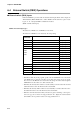
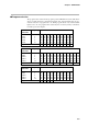
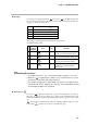
Table Of Contents
- CP-UM-5093E-04.pdf
- SAFETY PRECAUTIONS
- Contents
- Chapter 1. GENERAL
- Chapter 2. NAMES & FUNCTIONS OF PARTS
- Chapter 3. MOUNTING
- Chapter 4. WIRING
- 4-1 Wiring Precautions
- 4-2 Compensating Lead
- 4-3 Terminal Connections
- 4-4 Layout of Terminals and Recommended Lead Draw-out Direction
- 4-5 Connecting the Ground and Power Supply
- 4-6 Wiring of Standard and Add-on Terminal Base
- 4-7 Connecting Inputs (analog inputs)
- 4-8 Connecting control outputs (outputs 1, 2)
- 4-9 Connecting auxiliary outputs (outputs 2, 3)
- 4-10 Connecting Event Output (relay output)
- 4-11 Connecting Time Event Output (open-collector)
- 4-12 Connecting External Switch (RSW) Input
- 4-13 Connecting for Communications
- 4-14 Isolating Inputs and Outputs
- Chapter 5. FUNCTIONS
- Chapter 6. OPERATION
- Chapter 7. PARAMETER SETUP
- Chapter 8. PROGRAM SETUP
- Chapter 9. TROUBLESHOOTING
- Chapter 10. SPECIFICATIONS
- Chapter 11. CALIBRATION
- Index
Chapter 7. PARAMETER SETUP
7-4
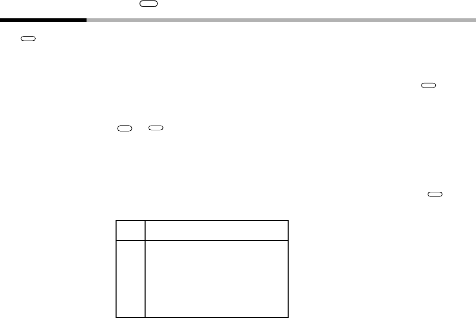
7-2 How to Use
PARA
Use
PARA
for calling up individual items in frequently changed parameters.
■ How to register functions to keys
Up to eight individual items in the parameter setup can be assigned to each
PARA
key. The
assignment item must be registered to use this feature.
This feature allows you to call up individual items more easily in the following order:
FUNC
+
PARA
→ selection of setting group → individual item matrix.
● How to register assignment items
To register an assignment item, add the following base corresponding to the setting group
to the item No., and then set the resultant value to setup data C 5 5 to C 6 2 (
PARA
assign-
ment items 1 to 8)).
Base Setting Group
1000 Constant-value operation data
1500 PID parameters
2500 Variable parameters
3500 Event configuration data
4000 Table data
4500 Setup data