
Clock Radio User Manual
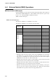
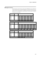
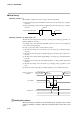
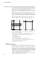
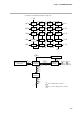
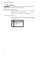
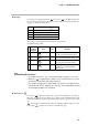
Table Of Contents
- CP-UM-5093E-04.pdf
- SAFETY PRECAUTIONS
- Contents
- Chapter 1. GENERAL
- Chapter 2. NAMES & FUNCTIONS OF PARTS
- Chapter 3. MOUNTING
- Chapter 4. WIRING
- 4-1 Wiring Precautions
- 4-2 Compensating Lead
- 4-3 Terminal Connections
- 4-4 Layout of Terminals and Recommended Lead Draw-out Direction
- 4-5 Connecting the Ground and Power Supply
- 4-6 Wiring of Standard and Add-on Terminal Base
- 4-7 Connecting Inputs (analog inputs)
- 4-8 Connecting control outputs (outputs 1, 2)
- 4-9 Connecting auxiliary outputs (outputs 2, 3)
- 4-10 Connecting Event Output (relay output)
- 4-11 Connecting Time Event Output (open-collector)
- 4-12 Connecting External Switch (RSW) Input
- 4-13 Connecting for Communications
- 4-14 Isolating Inputs and Outputs
- Chapter 5. FUNCTIONS
- Chapter 6. OPERATION
- Chapter 7. PARAMETER SETUP
- Chapter 8. PROGRAM SETUP
- Chapter 9. TROUBLESHOOTING
- Chapter 10. SPECIFICATIONS
- Chapter 11. CALIBRATION
- Index
Chapter 7. PARAMETER SETUP
7-3
• Example of individual item matrix (setup date)
Setting group selection
(major items)
Individual items
(minor items)
Setting value
blinking
Basic Display State
Change setting value.
ENT
key
ENT
key
PARA
key
DISP
key
ENT
key,
*
PARA
key
key
key
key
key
key
key
key
key
DISP
key
key
key,
key, key
Individual items
(minor items)
*
key stores setting values to memory.
key cancels storage of setting values to memory.
ENT
PARA
*
ENT
stores setting values to memory.
PARA
does not store setting values to memory.
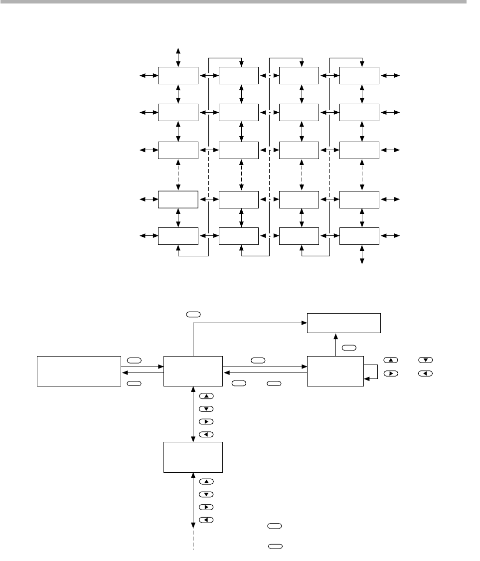
C0
1
C02
C03
C0
1
C02
C03
C
11
C
12
C
13
C8
1
C82
C83
C9
1
C92
C93
C9
1
C92
C93
C99
C00
C09
C10
C
19
C20
C
89
C90
C
99
C00
C0
1
C09
C
10
C00