
Clock Radio User Manual
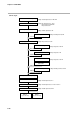
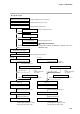
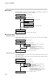
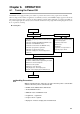
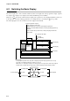
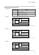
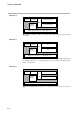
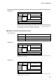
Table Of Contents
- CP-UM-5093E-04.pdf
- SAFETY PRECAUTIONS
- Contents
- Chapter 1. GENERAL
- Chapter 2. NAMES & FUNCTIONS OF PARTS
- Chapter 3. MOUNTING
- Chapter 4. WIRING
- 4-1 Wiring Precautions
- 4-2 Compensating Lead
- 4-3 Terminal Connections
- 4-4 Layout of Terminals and Recommended Lead Draw-out Direction
- 4-5 Connecting the Ground and Power Supply
- 4-6 Wiring of Standard and Add-on Terminal Base
- 4-7 Connecting Inputs (analog inputs)
- 4-8 Connecting control outputs (outputs 1, 2)
- 4-9 Connecting auxiliary outputs (outputs 2, 3)
- 4-10 Connecting Event Output (relay output)
- 4-11 Connecting Time Event Output (open-collector)
- 4-12 Connecting External Switch (RSW) Input
- 4-13 Connecting for Communications
- 4-14 Isolating Inputs and Outputs
- Chapter 5. FUNCTIONS
- Chapter 6. OPERATION
- Chapter 7. PARAMETER SETUP
- Chapter 8. PROGRAM SETUP
- Chapter 9. TROUBLESHOOTING
- Chapter 10. SPECIFICATIONS
- Chapter 11. CALIBRATION
- Index
Chapter 6. OPERATION
6-7
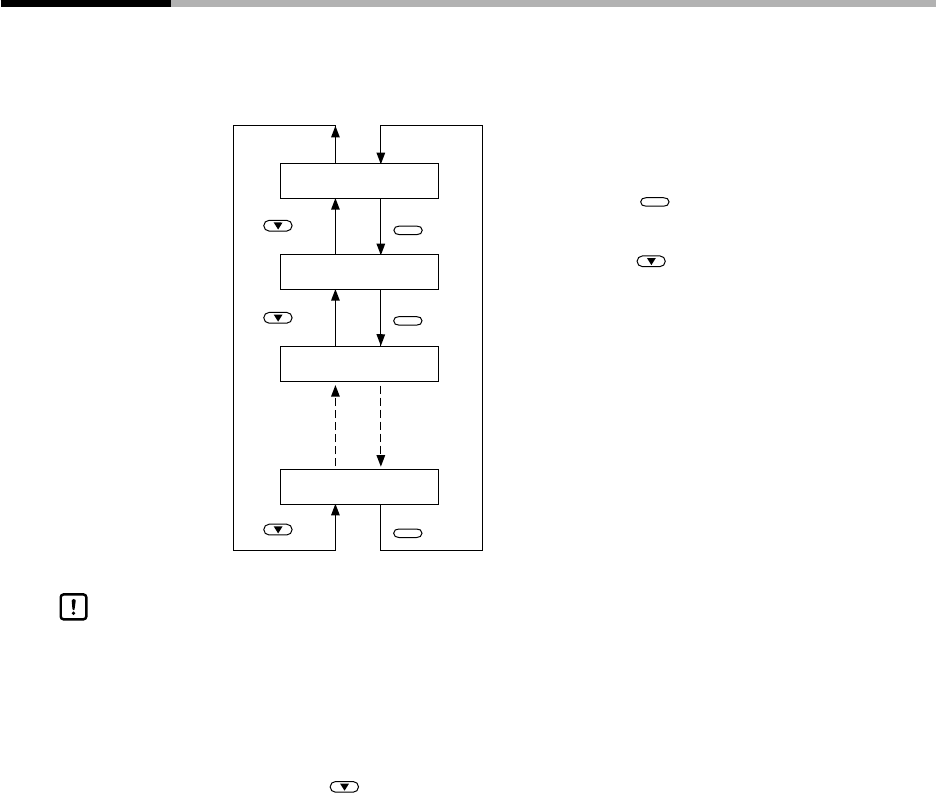
6-3 Program Selection
The program No. can be selected on the console within the range 1 to 19.
■ How to select the program No.
Program No.1
Program No.2
Program No.3
Program No.4
PROG
PROG
PROG
key
key
key
key
key
key
When the controller is in the basic display state in the
program operation READY mode:
• Each press of
PROG
increments the program No. The
display reverts to 1 after 19.
• Each press of decrements the program No. The
display reverts to 19 after 1.
• Both already set or non-set program Nos. can be selected
• The program No. cannot be selected when selecting the program No. by exter-
nal switch input.
• The program No. cannot be selected during constant-value operation.
• Pressing does not change the program No. when values currently being
entered are displayed in the MANUAL mode.
Handling Precautions