
Clock Radio User Manual
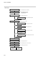
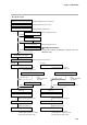
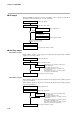
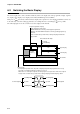
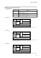
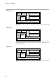
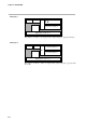
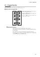
Table Of Contents
- CP-UM-5093E-04.pdf
- SAFETY PRECAUTIONS
- Contents
- Chapter 1. GENERAL
- Chapter 2. NAMES & FUNCTIONS OF PARTS
- Chapter 3. MOUNTING
- Chapter 4. WIRING
- 4-1 Wiring Precautions
- 4-2 Compensating Lead
- 4-3 Terminal Connections
- 4-4 Layout of Terminals and Recommended Lead Draw-out Direction
- 4-5 Connecting the Ground and Power Supply
- 4-6 Wiring of Standard and Add-on Terminal Base
- 4-7 Connecting Inputs (analog inputs)
- 4-8 Connecting control outputs (outputs 1, 2)
- 4-9 Connecting auxiliary outputs (outputs 2, 3)
- 4-10 Connecting Event Output (relay output)
- 4-11 Connecting Time Event Output (open-collector)
- 4-12 Connecting External Switch (RSW) Input
- 4-13 Connecting for Communications
- 4-14 Isolating Inputs and Outputs
- Chapter 5. FUNCTIONS
- Chapter 6. OPERATION
- Chapter 7. PARAMETER SETUP
- Chapter 8. PROGRAM SETUP
- Chapter 9. TROUBLESHOOTING
- Chapter 10. SPECIFICATIONS
- Chapter 11. CALIBRATION
- Index

Chapter 6. OPERATION
6-4
● Display 4
OUT
Heat-side output (%)
Cool-side output (%)
Program No. Segment No.
Pattern
tendency
Output states of events 1 to 3, time events 1 to 5
This display is exclusive to heat/cool output models (output catalog No. appended with
3D or 5K).
● Display 5
PV
TM
PV
Time
Program No. Segment No.
Pattern
tendency
Output states of events 1 to 3, time events 1 to 5
Either of “h:min” or “min:s” is selected as the time unit in setup settings. Select either
“remaining segment time” or “total operating time” in setup settings as the details whose
time is to be displayed.
● Display 6
PV
CYC
PV
Number of remaining cycles
Program No. Segment No.
Pattern
tendency
Output states of events 1 to 3, time events 1 to 5
When the remaining number of cycles is “0”, subsequent cycle operation is not carried
out.