
Clock Radio User Manual
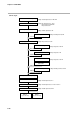
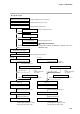
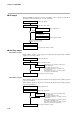
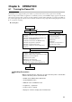
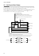
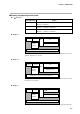
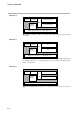
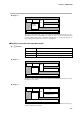
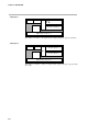
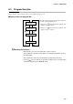
Table Of Contents
- CP-UM-5093E-04.pdf
- SAFETY PRECAUTIONS
- Contents
- Chapter 1. GENERAL
- Chapter 2. NAMES & FUNCTIONS OF PARTS
- Chapter 3. MOUNTING
- Chapter 4. WIRING
- 4-1 Wiring Precautions
- 4-2 Compensating Lead
- 4-3 Terminal Connections
- 4-4 Layout of Terminals and Recommended Lead Draw-out Direction
- 4-5 Connecting the Ground and Power Supply
- 4-6 Wiring of Standard and Add-on Terminal Base
- 4-7 Connecting Inputs (analog inputs)
- 4-8 Connecting control outputs (outputs 1, 2)
- 4-9 Connecting auxiliary outputs (outputs 2, 3)
- 4-10 Connecting Event Output (relay output)
- 4-11 Connecting Time Event Output (open-collector)
- 4-12 Connecting External Switch (RSW) Input
- 4-13 Connecting for Communications
- 4-14 Isolating Inputs and Outputs
- Chapter 5. FUNCTIONS
- Chapter 6. OPERATION
- Chapter 7. PARAMETER SETUP
- Chapter 8. PROGRAM SETUP
- Chapter 9. TROUBLESHOOTING
- Chapter 10. SPECIFICATIONS
- Chapter 11. CALIBRATION
- Index
Chapter 6. OPERATION
6-2
6-2 Switching the Basic Display
The “basic display state” of the controller collectively refers to the display state of the program No. display, segment
No. display, upper display, lower display, basic indicator LED lamps and event LEDs.
Each press of
DISP
successively switches the basic display state. Operation of other displays and LEDs is carried out
in the same way even when setting up parameters, for example. However, switching by
DISP
is not possible.
The following figure shows the conventions used for displays in this manual.
PROFILE
(2)
(1)
(3)
(4)
(5)
(6)
Current segment Next segment
Falling ramp
Soak
Rising ramp
Rising ramp
Soak
Falling ramp
PV
SP
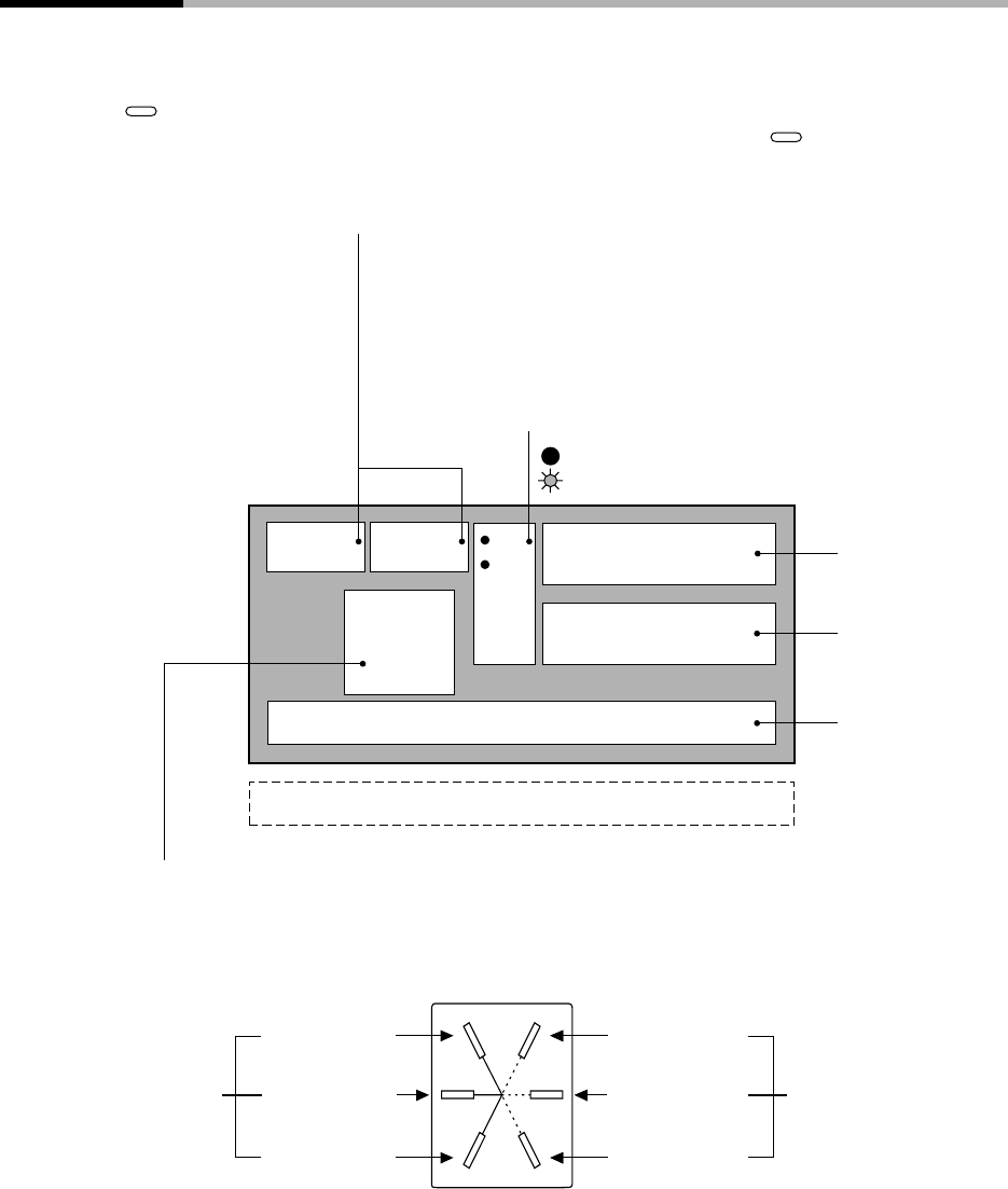
: LED lit
: LED blinking
PV
SP
Program/segment No. Display
Basic indicator LED lamps
Program No. Segment No.
Pattern
tendency
Upper display
Lower display
Event LEDs
Output states of events 1 to 3, time events 1 to 5
Supplementary explanation
In the program operation mode,
READY indicates the currently selected program/segment No.
Displays other than READY indicate the currently operating program/seg-
ment No.
In the constant-value operation mode, nothing is displayed and this dis-
play is blank.
In the program operation mode, the profile is displayed only when the program has been set up.
The profile is not displayed when the program is not set up.
When there is no subsequent segment even if the program is set up, the three LEDs on the right do
not light. In the constant-value operation mode, nothing is displayed and this display is blank.
Profile Display