
Clock Radio User Manual
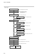
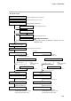
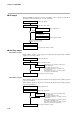
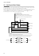
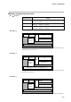
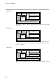
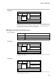
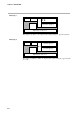
Table Of Contents
- CP-UM-5093E-04.pdf
- SAFETY PRECAUTIONS
- Contents
- Chapter 1. GENERAL
- Chapter 2. NAMES & FUNCTIONS OF PARTS
- Chapter 3. MOUNTING
- Chapter 4. WIRING
- 4-1 Wiring Precautions
- 4-2 Compensating Lead
- 4-3 Terminal Connections
- 4-4 Layout of Terminals and Recommended Lead Draw-out Direction
- 4-5 Connecting the Ground and Power Supply
- 4-6 Wiring of Standard and Add-on Terminal Base
- 4-7 Connecting Inputs (analog inputs)
- 4-8 Connecting control outputs (outputs 1, 2)
- 4-9 Connecting auxiliary outputs (outputs 2, 3)
- 4-10 Connecting Event Output (relay output)
- 4-11 Connecting Time Event Output (open-collector)
- 4-12 Connecting External Switch (RSW) Input
- 4-13 Connecting for Communications
- 4-14 Isolating Inputs and Outputs
- Chapter 5. FUNCTIONS
- Chapter 6. OPERATION
- Chapter 7. PARAMETER SETUP
- Chapter 8. PROGRAM SETUP
- Chapter 9. TROUBLESHOOTING
- Chapter 10. SPECIFICATIONS
- Chapter 11. CALIBRATION
- Index
Chapter 5. FUNCTIONS
5-21
READY mode
MANUAL mode
READY/AUTO modes READY/AUTO modes
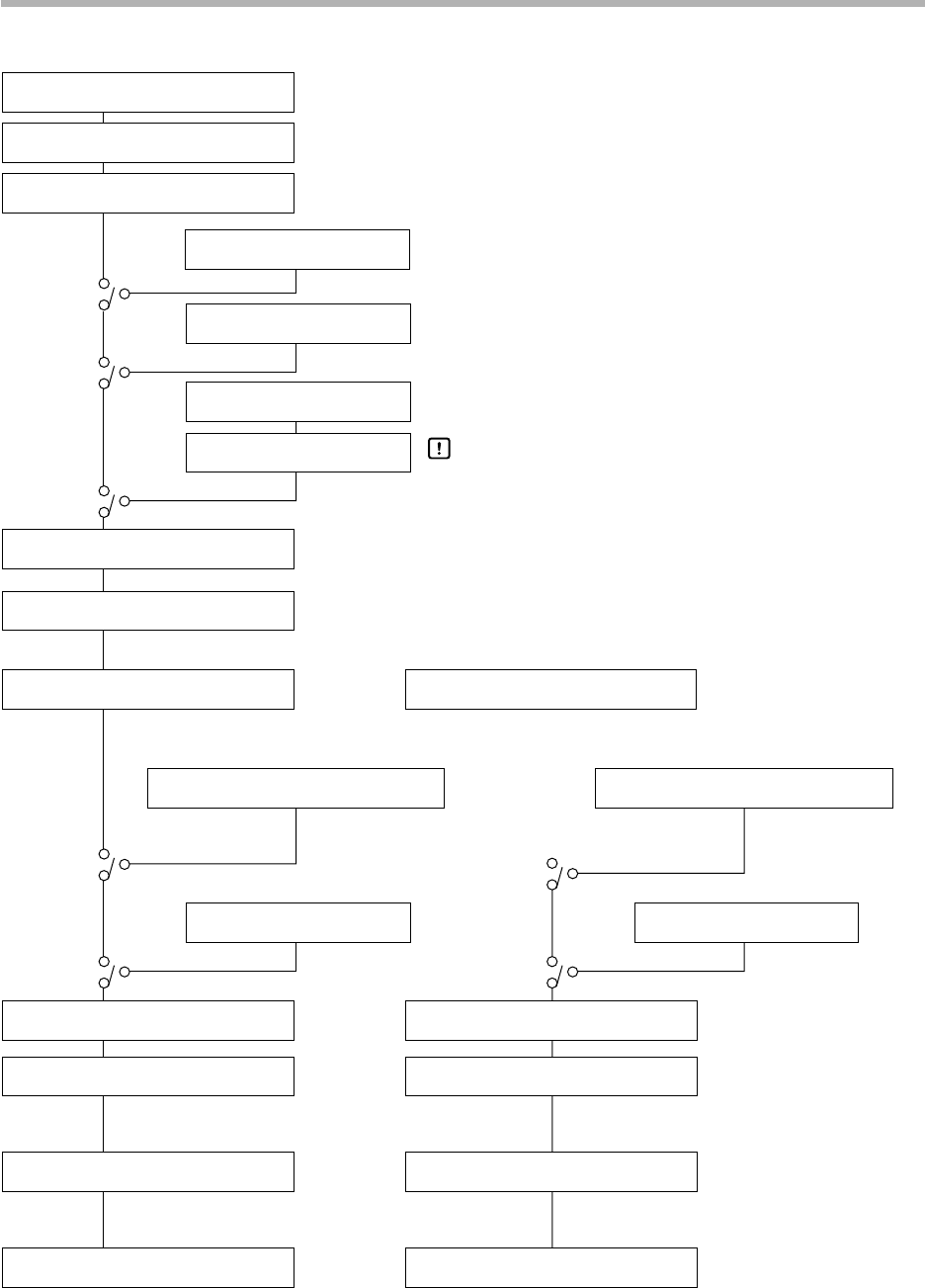
Time-proportional relay output
Current output 4 to 20mA (0 to 20mA)
Time-proportional voltage output
PID control operation
Initialization of PID control operation
Output change limitter
(odd-numbered PID sets)
Output upper/lower limit limitter
(even-numbered PID sets)
Heat-side Cool-side
Output upper/lower limit limitter
MV (heat)
Output 1 time-proportional output cycle
Voltage output 1 adjustment
Output 1
Time-proportional relay output
Current output 4 to 20mA (0 to 20mA)
Time-proportional voltage output
MV (cool)
Output 2 time-proportional output cycle
Voltage output 2 adjustment
Output 2
Manipulated variable (MV1)
Heat-cool MV operation
Over-range
Manual MV
3-position control
3-position control operation
Preset manual value
MV in READY mode (heat)
3-position control
MV in READY mode (cool)
3-position control operation
50%
MV at over-range
Setting: Variable parameters 1 OUT/rpi d
Setting: PID parameters p/ 1 / d/RE
Setting: Variable parameters OTL
Setting: Setup data C 12/C 13
Setting: Setup data C 14/C 15
Setting: Variable parameter DI FF
Setting: PID parameters OL/OH
Setting: Setup data C 16
Setting: Setup data C 17
(relay/voltage output)
Setting: Variable parameter CY. 1
(relay/voltage output)
Setting: Variable parameter CY.2
(voltage output)
Setting: Setup data C78
(voltage output)
Setting: Setup data C79
Setting: PID parameters OL/OH
Setting: Setup data
Variable parameters
C45
Dv-L/HY-L
Setting: Setup data
Variable parameters
C45
Dv-H/HY-H
● 3D, 5K outputs
In 3-position control, the DCP301 cannot be set to the
MANUAL mode
Handling Precautions