
Clock Radio User Manual
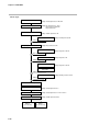
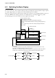
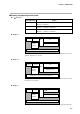
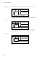
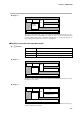
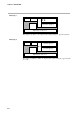
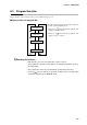
Table Of Contents
- CP-UM-5093E-04.pdf
- SAFETY PRECAUTIONS
- Contents
- Chapter 1. GENERAL
- Chapter 2. NAMES & FUNCTIONS OF PARTS
- Chapter 3. MOUNTING
- Chapter 4. WIRING
- 4-1 Wiring Precautions
- 4-2 Compensating Lead
- 4-3 Terminal Connections
- 4-4 Layout of Terminals and Recommended Lead Draw-out Direction
- 4-5 Connecting the Ground and Power Supply
- 4-6 Wiring of Standard and Add-on Terminal Base
- 4-7 Connecting Inputs (analog inputs)
- 4-8 Connecting control outputs (outputs 1, 2)
- 4-9 Connecting auxiliary outputs (outputs 2, 3)
- 4-10 Connecting Event Output (relay output)
- 4-11 Connecting Time Event Output (open-collector)
- 4-12 Connecting External Switch (RSW) Input
- 4-13 Connecting for Communications
- 4-14 Isolating Inputs and Outputs
- Chapter 5. FUNCTIONS
- Chapter 6. OPERATION
- Chapter 7. PARAMETER SETUP
- Chapter 8. PROGRAM SETUP
- Chapter 9. TROUBLESHOOTING
- Chapter 10. SPECIFICATIONS
- Chapter 11. CALIBRATION
- Index
Chapter 5. FUNCTIONS
5-20
● 2G output
Over-range
READY mode
MFB automatic
adjustment execution
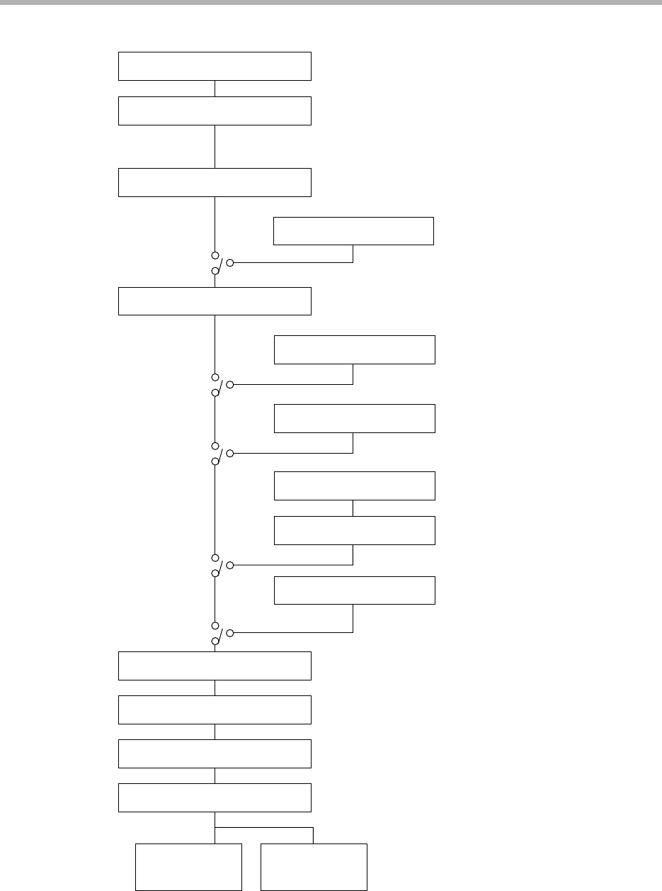
PID control operation
Initialization of PID control operation
Output change limitter
Output upper/lower limit limitter
MFB operation
Motor control operation
Manipulated variable (MV1)
Motor control method selection
AT execution
MV in READY mode
MANUAL mode
Manual MV
Preset manual value
MFB automatic adjustment
MV at over-range
AT operation
Output 1
open-side relay
Output 1
closed-side relay
Setting: Variable parameters 1 OUT/rpi d
Setting: PID parameters p/ 1 / d/RE
PID parameters dP/di /dd
PID parameters br
Setting: Variable parameters OTL
Setting: Variable parameter AT
Setting: PID parameters OL/OH
Setting: Setup data C 12/C 13
Setting: Setup data C 14/C 15
Setting: Setup data C 16
Setting: Variable parameter DI FF
Setting: Variable parameter M.-AT
Setting: Variable parameter M.-C
Setting: Variable parameters M.-CL/M.-OP/M.-T