
Clock Radio User Manual
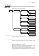
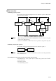
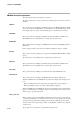
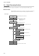
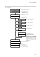
Table Of Contents
- CP-UM-5093E-04.pdf
- SAFETY PRECAUTIONS
- Contents
- Chapter 1. GENERAL
- Chapter 2. NAMES & FUNCTIONS OF PARTS
- Chapter 3. MOUNTING
- Chapter 4. WIRING
- 4-1 Wiring Precautions
- 4-2 Compensating Lead
- 4-3 Terminal Connections
- 4-4 Layout of Terminals and Recommended Lead Draw-out Direction
- 4-5 Connecting the Ground and Power Supply
- 4-6 Wiring of Standard and Add-on Terminal Base
- 4-7 Connecting Inputs (analog inputs)
- 4-8 Connecting control outputs (outputs 1, 2)
- 4-9 Connecting auxiliary outputs (outputs 2, 3)
- 4-10 Connecting Event Output (relay output)
- 4-11 Connecting Time Event Output (open-collector)
- 4-12 Connecting External Switch (RSW) Input
- 4-13 Connecting for Communications
- 4-14 Isolating Inputs and Outputs
- Chapter 5. FUNCTIONS
- Chapter 6. OPERATION
- Chapter 7. PARAMETER SETUP
- Chapter 8. PROGRAM SETUP
- Chapter 9. TROUBLESHOOTING
- Chapter 10. SPECIFICATIONS
- Chapter 11. CALIBRATION
- Index
Chapter 5. FUNCTIONS
5-17
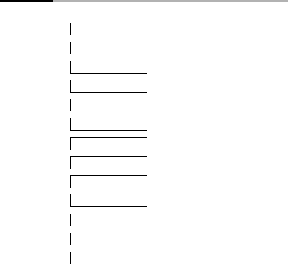
5-5 Input Processing Functions
Input processing is carried out in the order shown below.
(resistance temperature detector)
(thermocouple)
Input range type
Wiring resistance compensation
Analog input 1
A/D conversion
Cold junction compensation
Upper/lower limit value scaling
Upper/lower limit alarm
Square-root extraction
Temperature unit range
Linearization approximation
Digital filter
Bias
PV1
(DC current and voltage)
Setting: Setup data
C03
Setting: Setup data
C72
Setting: Setup data
C0 7
(thermocouple and resistance temperature detector)
Setting: Setup data
C02
(DC current and voltage)
Setting: Setup data
C0 4
to
C06
Setting: Setup data
C08
Table data
T-A.
1
to
T-B.B
Setting: Variable parameter
FL
Setting: Variable parameter
PBi