
Clock Radio User Manual
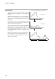
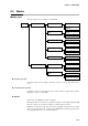
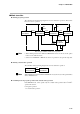
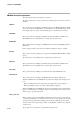
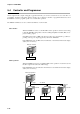
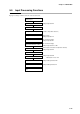
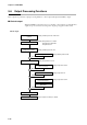
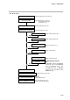
Table Of Contents
- CP-UM-5093E-04.pdf
- SAFETY PRECAUTIONS
- Contents
- Chapter 1. GENERAL
- Chapter 2. NAMES & FUNCTIONS OF PARTS
- Chapter 3. MOUNTING
- Chapter 4. WIRING
- 4-1 Wiring Precautions
- 4-2 Compensating Lead
- 4-3 Terminal Connections
- 4-4 Layout of Terminals and Recommended Lead Draw-out Direction
- 4-5 Connecting the Ground and Power Supply
- 4-6 Wiring of Standard and Add-on Terminal Base
- 4-7 Connecting Inputs (analog inputs)
- 4-8 Connecting control outputs (outputs 1, 2)
- 4-9 Connecting auxiliary outputs (outputs 2, 3)
- 4-10 Connecting Event Output (relay output)
- 4-11 Connecting Time Event Output (open-collector)
- 4-12 Connecting External Switch (RSW) Input
- 4-13 Connecting for Communications
- 4-14 Isolating Inputs and Outputs
- Chapter 5. FUNCTIONS
- Chapter 6. OPERATION
- Chapter 7. PARAMETER SETUP
- Chapter 8. PROGRAM SETUP
- Chapter 9. TROUBLESHOOTING
- Chapter 10. SPECIFICATIONS
- Chapter 11. CALIBRATION
- Index

Chapter 5. FUNCTIONS
5-11
5-3 Modes
■ Mode types
The following modes are available on the DCP301.
READY
AUTO
MANUAL
AUTO
MANUAL
AUTO
MANUAL
AUTO
MANUAL
AUTO
MANUAL
AUTO
MANUAL
AUTO
MANUAL
RUN
HOLD
END
FAST
READY
Program operationMode
Constant-value operation
RUN
● Program operation
Operation is carried out according to SP, times, events, etc. set to program patterns No.1
to 19.
● Constant-value operation
Operation is carried out according to SP or events set in the constant-value operation
data. Time events 1 to 5 turn OFF.
● READY
In this mode, the DCP301 is ready for operation.
MV output is fixed, and events to be operated according to event setting values turn OFF.
However, events to be operated according to controller states are active.
Parameters for all of the setup data, some event configuration data and some constant-
value operation data can be set or changed in the READY mode. During program opera-
tion, program pattern Nos.1 to 19 can be selected.