
Clock Radio User Manual
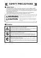
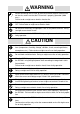
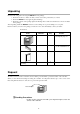
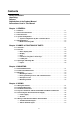
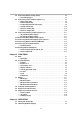
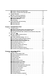
Table Of Contents
- CP-UM-5093E-04.pdf
- SAFETY PRECAUTIONS
- Contents
- Chapter 1. GENERAL
- Chapter 2. NAMES & FUNCTIONS OF PARTS
- Chapter 3. MOUNTING
- Chapter 4. WIRING
- 4-1 Wiring Precautions
- 4-2 Compensating Lead
- 4-3 Terminal Connections
- 4-4 Layout of Terminals and Recommended Lead Draw-out Direction
- 4-5 Connecting the Ground and Power Supply
- 4-6 Wiring of Standard and Add-on Terminal Base
- 4-7 Connecting Inputs (analog inputs)
- 4-8 Connecting control outputs (outputs 1, 2)
- 4-9 Connecting auxiliary outputs (outputs 2, 3)
- 4-10 Connecting Event Output (relay output)
- 4-11 Connecting Time Event Output (open-collector)
- 4-12 Connecting External Switch (RSW) Input
- 4-13 Connecting for Communications
- 4-14 Isolating Inputs and Outputs
- Chapter 5. FUNCTIONS
- Chapter 6. OPERATION
- Chapter 7. PARAMETER SETUP
- Chapter 8. PROGRAM SETUP
- Chapter 9. TROUBLESHOOTING
- Chapter 10. SPECIFICATIONS
- Chapter 11. CALIBRATION
- Index
E
N
1
I
-
X
X
X
X
I
s
s
u
e
X
(
X
X
/
X
X
)
X
X
X
X
XX
X
X
X
X
X
X
X
X
X
X
X
X
X
X
X
X
XX
X
XX
X
X
U
ser
s M
an
u
al
Unpacking
iv
Check the following when removing the DCP301 from its package.
1. Check the model No. to make sure that you have received the product that you ordered.
2. Check the DCP301 for any apparent physical damage.
3. Check the contents of the package against the Package List to make sure that all accessories are included
in the package.
After unpacking, handle the DCP301 and its accessories taking care to prevent damage or loss of parts.
If an inconsistency is found or the package contents are not in order, immediately contact your dealer.
Name Model No. Q’ty Remarks
See 1-5 How Model Nos.
Are Configured, page 1-5.
1
Mounting bracket
81405411-001
1 set (2)
User's Manual EN1I-6197
1
This manual
Unit indicator label
(SI units)
N-3132
1
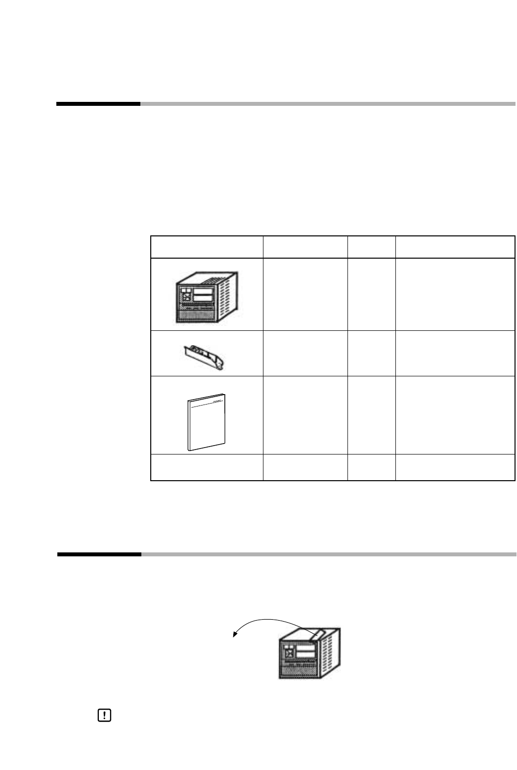
Request
The filter on the front of the controller is Covered with a protective film to protect the surface of the controller.
When you have finished mounting and wiring the controller, fix cellophane adhesive tape on the corners of the
filter, and pull in the direction of the arrow to peel off the protective film.
The Model No. is the parts
No. for two installation tools.
Product List
Pull towards you.
Handling Precautions
Peeling off the protective film with your fingernail might scratch the
surface of the controller.
Body