
Clock Radio User Manual
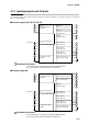
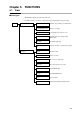
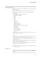
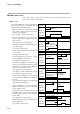
Table Of Contents
- CP-UM-5093E-04.pdf
- SAFETY PRECAUTIONS
- Contents
- Chapter 1. GENERAL
- Chapter 2. NAMES & FUNCTIONS OF PARTS
- Chapter 3. MOUNTING
- Chapter 4. WIRING
- 4-1 Wiring Precautions
- 4-2 Compensating Lead
- 4-3 Terminal Connections
- 4-4 Layout of Terminals and Recommended Lead Draw-out Direction
- 4-5 Connecting the Ground and Power Supply
- 4-6 Wiring of Standard and Add-on Terminal Base
- 4-7 Connecting Inputs (analog inputs)
- 4-8 Connecting control outputs (outputs 1, 2)
- 4-9 Connecting auxiliary outputs (outputs 2, 3)
- 4-10 Connecting Event Output (relay output)
- 4-11 Connecting Time Event Output (open-collector)
- 4-12 Connecting External Switch (RSW) Input
- 4-13 Connecting for Communications
- 4-14 Isolating Inputs and Outputs
- Chapter 5. FUNCTIONS
- Chapter 6. OPERATION
- Chapter 7. PARAMETER SETUP
- Chapter 8. PROGRAM SETUP
- Chapter 9. TROUBLESHOOTING
- Chapter 10. SPECIFICATIONS
- Chapter 11. CALIBRATION
- Index
Chapter 5. FUNCTIONS
5-1
Chapter 5. FUNCTIONS
5-1 Data
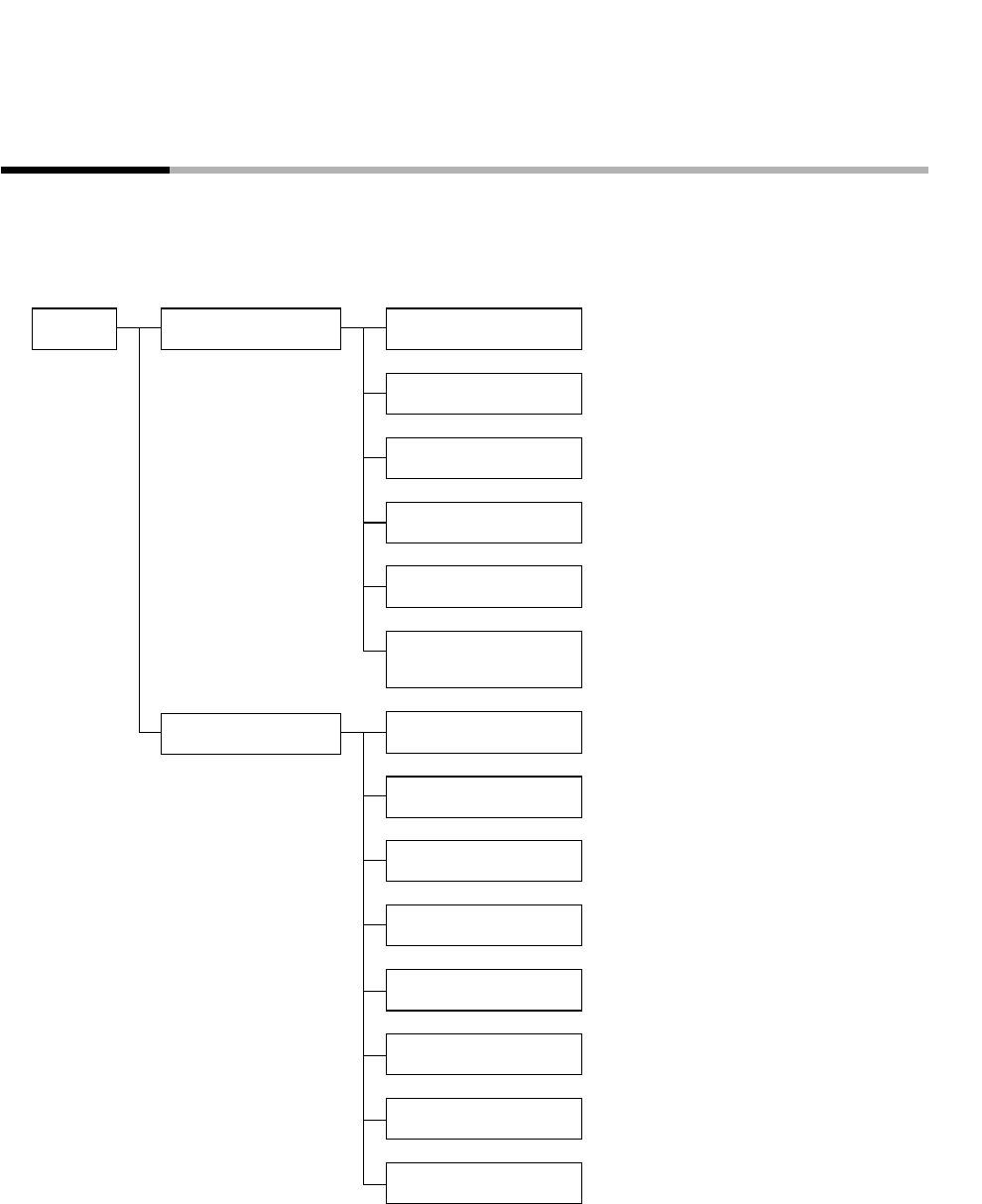
■ Data types
The DCP301 supports the following data types.
For further details, see Chapter 7, Parameter Setup and Chapter 8, Program Setup.
Data that can be changed even in RUN mode
Data Parameters
Program
Data (e.g. event type)
Control parameters of PID sets 1 to 8
Basic data that can be changed only in
READY mode
Linearization table data
Data (e.g. SP, PID) of constant-value operation
SP and time data
Events 1 to 3 data
Time events 1 to 5 time data
PID set No. data for use in control
G.Soak ON/OFF data
PV START ON/OFF data
Cycle count data
Pattern link destination program No. data
Variable parameters
Event configuration data
PID parameters
Setup data
Table data
Constant-value operation
data
Pattern
Event
Time event
PID set No.
G.Soak
PV start
Cycle
Pattern link