
Clock Radio User Manual
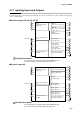
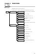
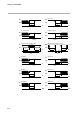
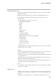
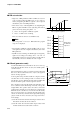
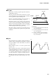
Table Of Contents
- CP-UM-5093E-04.pdf
- SAFETY PRECAUTIONS
- Contents
- Chapter 1. GENERAL
- Chapter 2. NAMES & FUNCTIONS OF PARTS
- Chapter 3. MOUNTING
- Chapter 4. WIRING
- 4-1 Wiring Precautions
- 4-2 Compensating Lead
- 4-3 Terminal Connections
- 4-4 Layout of Terminals and Recommended Lead Draw-out Direction
- 4-5 Connecting the Ground and Power Supply
- 4-6 Wiring of Standard and Add-on Terminal Base
- 4-7 Connecting Inputs (analog inputs)
- 4-8 Connecting control outputs (outputs 1, 2)
- 4-9 Connecting auxiliary outputs (outputs 2, 3)
- 4-10 Connecting Event Output (relay output)
- 4-11 Connecting Time Event Output (open-collector)
- 4-12 Connecting External Switch (RSW) Input
- 4-13 Connecting for Communications
- 4-14 Isolating Inputs and Outputs
- Chapter 5. FUNCTIONS
- Chapter 6. OPERATION
- Chapter 7. PARAMETER SETUP
- Chapter 8. PROGRAM SETUP
- Chapter 9. TROUBLESHOOTING
- Chapter 10. SPECIFICATIONS
- Chapter 11. CALIBRATION
- Index
Chapter 4. WIRING
4-19
4-14 Isolating Inputs and Outputs
The following figures show isolation between inputs and outputs. Solid lines show isolated items, and dotted lines
show non-isolated items.
■ Control outputs 0D, 5G, 6D, 3D, 5K
31
11
12
14
15
17
18
4
5
6
7
8
9
10
49
56
32
33
34
21
25
41
48
57
61
Input 1
(full multiple-input PV
supported)
Output 1
(relay, current, voltage output)
Output 2
(relay, current, voltage output,
auxiliary output)
Output 3
(auxiliary output)
Event output 1
(relay output 1a)
Event output 2
(relay output 1a)
Event output 3
(relay output 1a1b)
Time event outputs 1 to 5
(open-collector output)
Loader communications
I/O
Loader jack
12 external switch inputs
Communications I/O
(RS-485)
Digital circuit
31
11
12
13
14
15
16
17
18
4
5
6
7
8
9
10
49
56
32
33
34
21
25
41
48
57
61
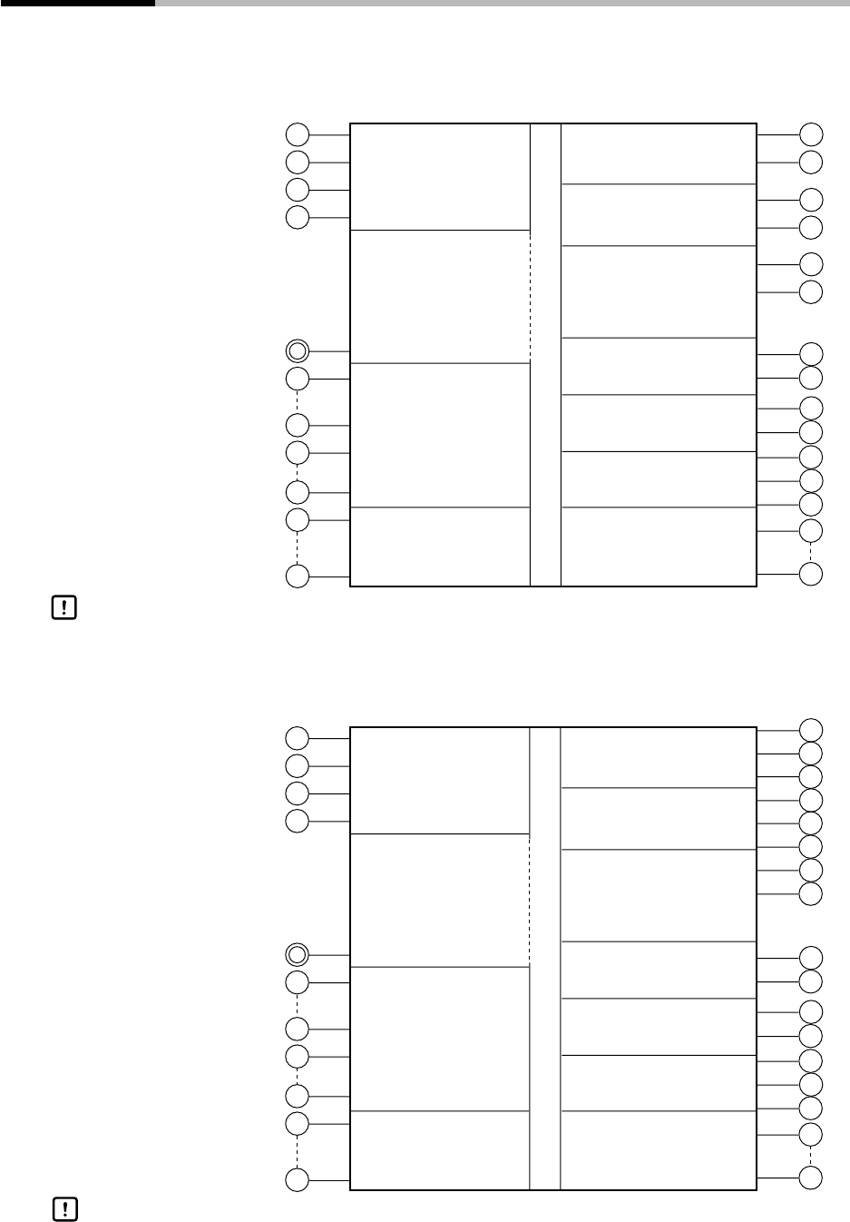
Input 1
(full multiple-input PV
supported)
Output 1
(control output 1a relay x 2)
Motor feedback input
Output 3
(auxiliary output)
Event output 1
(relay output 1a)
Event output 2
(relay output 1a)
Event output 3
(relay output 1a1b)
Time event outputs 1 to 5
(open-collector output)
Loader communications
I/O
Loader jack
12 external switch inputs
Communications I/O
(RS-485)
Digital circuit
The loader jack is not isolated from internal digital circuits.
Be sure to cap the loader jack when it is not in use.
■ Control output 2G
Handling Precautions
Handling Precautions
The loader jack is not isolated from internal digital circuits.
Be sure to cap the loader jack when it is not in use.