
Clock Radio User Manual
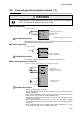
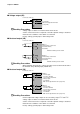
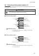
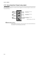
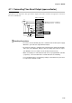
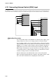
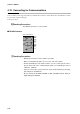
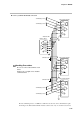
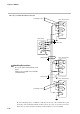
Table Of Contents
- CP-UM-5093E-04.pdf
- SAFETY PRECAUTIONS
- Contents
- Chapter 1. GENERAL
- Chapter 2. NAMES & FUNCTIONS OF PARTS
- Chapter 3. MOUNTING
- Chapter 4. WIRING
- 4-1 Wiring Precautions
- 4-2 Compensating Lead
- 4-3 Terminal Connections
- 4-4 Layout of Terminals and Recommended Lead Draw-out Direction
- 4-5 Connecting the Ground and Power Supply
- 4-6 Wiring of Standard and Add-on Terminal Base
- 4-7 Connecting Inputs (analog inputs)
- 4-8 Connecting control outputs (outputs 1, 2)
- 4-9 Connecting auxiliary outputs (outputs 2, 3)
- 4-10 Connecting Event Output (relay output)
- 4-11 Connecting Time Event Output (open-collector)
- 4-12 Connecting External Switch (RSW) Input
- 4-13 Connecting for Communications
- 4-14 Isolating Inputs and Outputs
- Chapter 5. FUNCTIONS
- Chapter 6. OPERATION
- Chapter 7. PARAMETER SETUP
- Chapter 8. PROGRAM SETUP
- Chapter 9. TROUBLESHOOTING
- Chapter 10. SPECIFICATIONS
- Chapter 11. CALIBRATION
- Index
Chapter 4. WIRING
4-17
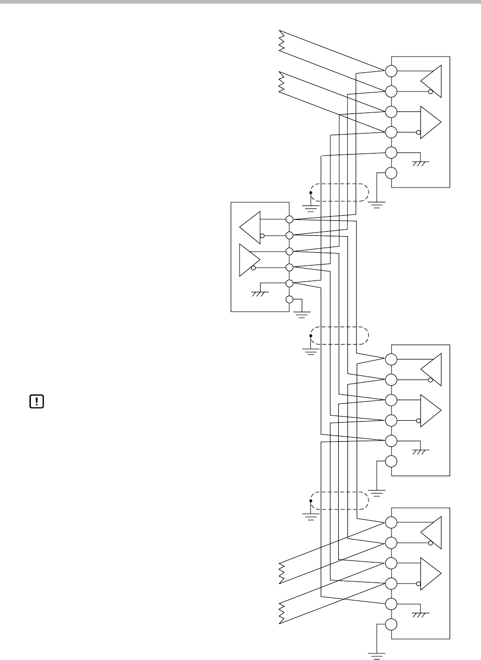
● 5-wire system RS-485 mutual connection
57
58
59
60
61
SDA
SDB
RDA
RDB
SG
FG
57
58
59
60
61
SDA
SDB
RDA
RDB
RDA
RDB
SDA
SDB
SG
FG
SG
FG
57
58
59
60
61
SDA
SDB
RDA
RDB
SG
FG
Terminating resistor
Terminating resistor
Terminating resistor
Terminating resistor
Slave station DCP301
Shielded cable
Shielded cable
Shielded cable
Master station
Slave station DCP301
Slave station DCP301
Provide terminating resistor of 150Ω±5%, 1/2W min. at both ends of the communications path.
Grounding of the shielded FG terminal should be carried out at only one end and not both ends.
Be sure to connect SG terminals each
others.
Failure to do so might cause unstable
communications.
Handling Precautions