
Clock Radio User Manual
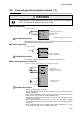
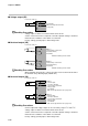
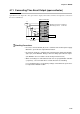
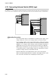
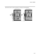
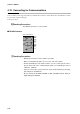
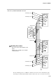
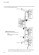
Table Of Contents
- CP-UM-5093E-04.pdf
- SAFETY PRECAUTIONS
- Contents
- Chapter 1. GENERAL
- Chapter 2. NAMES & FUNCTIONS OF PARTS
- Chapter 3. MOUNTING
- Chapter 4. WIRING
- 4-1 Wiring Precautions
- 4-2 Compensating Lead
- 4-3 Terminal Connections
- 4-4 Layout of Terminals and Recommended Lead Draw-out Direction
- 4-5 Connecting the Ground and Power Supply
- 4-6 Wiring of Standard and Add-on Terminal Base
- 4-7 Connecting Inputs (analog inputs)
- 4-8 Connecting control outputs (outputs 1, 2)
- 4-9 Connecting auxiliary outputs (outputs 2, 3)
- 4-10 Connecting Event Output (relay output)
- 4-11 Connecting Time Event Output (open-collector)
- 4-12 Connecting External Switch (RSW) Input
- 4-13 Connecting for Communications
- 4-14 Isolating Inputs and Outputs
- Chapter 5. FUNCTIONS
- Chapter 6. OPERATION
- Chapter 7. PARAMETER SETUP
- Chapter 8. PROGRAM SETUP
- Chapter 9. TROUBLESHOOTING
- Chapter 10. SPECIFICATIONS
- Chapter 11. CALIBRATION
- Index

Chapter 4. WIRING
4-16
4-13 Connecting for Communications
Some controller models support the RS-485 communications interface. Select the RS-485 communications models
by selected the required catalog No.
Connect as follows.
The DCP301 operates as a slave station.
■ RS-485 interface
57
58
59
60
61
SDA
SDB
RDA
RDB
SG
Add-on terminal base
• Multi-drop connection of slave stations is possible.
• Make sure that different addresses are set for each slave station.
• Provide terminating resistor (total of 4 in the case of a 5-wire system connec-
tion) on both ends of the communications path. Use terminating resistor of
150Ω±5%, 1/2W min.
• In the case of a 3-wire system connection, short-circuit terminals (57) and (59),
(58) and (60) on the DCP301.
• Do not short-circuit the RDA and RDB, or SDA and SDB terminals. Doing so
might damage the DCP301.
Handling Precautions
Handling Precautions