
Clock Radio User Manual
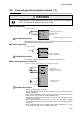
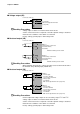
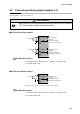
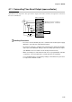
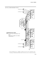
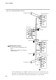
Table Of Contents
- CP-UM-5093E-04.pdf
- SAFETY PRECAUTIONS
- Contents
- Chapter 1. GENERAL
- Chapter 2. NAMES & FUNCTIONS OF PARTS
- Chapter 3. MOUNTING
- Chapter 4. WIRING
- 4-1 Wiring Precautions
- 4-2 Compensating Lead
- 4-3 Terminal Connections
- 4-4 Layout of Terminals and Recommended Lead Draw-out Direction
- 4-5 Connecting the Ground and Power Supply
- 4-6 Wiring of Standard and Add-on Terminal Base
- 4-7 Connecting Inputs (analog inputs)
- 4-8 Connecting control outputs (outputs 1, 2)
- 4-9 Connecting auxiliary outputs (outputs 2, 3)
- 4-10 Connecting Event Output (relay output)
- 4-11 Connecting Time Event Output (open-collector)
- 4-12 Connecting External Switch (RSW) Input
- 4-13 Connecting for Communications
- 4-14 Isolating Inputs and Outputs
- Chapter 5. FUNCTIONS
- Chapter 6. OPERATION
- Chapter 7. PARAMETER SETUP
- Chapter 8. PROGRAM SETUP
- Chapter 9. TROUBLESHOOTING
- Chapter 10. SPECIFICATIONS
- Chapter 11. CALIBRATION
- Index

Chapter 4. WIRING
4-14
4-12 Connecting External Switch (RSW) Input
The DCP301 is provided with four external switch inputs as standard (eight optional). The optional eight inputs are
located on the add-on terminal base. Wire the external switch inputs across the standard and add-on terminal bases.
25
23
24
21
22
RSW1
RSW2
RSW3
RSW4
COM
45
43
44
41
42
48
46
47
RSW5
RSW6
RSW7
RSW8
RSW10
RSW11
RSW12
RSW9
Add-on terminal base
Standard terminal base
Contact
Contact
Contact
Contact
Contact
Contact
Contact
Contact
Contact
Contact
Contact
Contact
• The external switch inputs on the DCP301 have built-in power supplies (open
voltage 12Vdc). Be sure to use no-voltage contacts for external contacts.
• Use no-voltage contacts such as gold contacts whose small current can be
switched ON/OFF. On some relay contacts, the small current cannot be switched
ON/OFF. Use no-voltage contacts having a sufficient minimum switching ca-
pability with respect to the contact current and open voltage of the DCP301.
• When using a semiconductor (e.g. open-collector) as a no-voltage contact, use
a semiconductor whose contact terminal voltages at contact ON are 3V max.,
and whose leakage current at contact OFF is 0.1mA.
• External switch inputs on the DCP301/302 can be connected in parallel.
When connecting in parallel with other controllers, thoroughly check the condi-
tions of the other controller before configuring the control system.
Handling Precautions