
Clock Radio User Manual
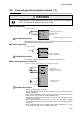
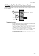
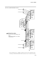
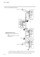
Table Of Contents
- CP-UM-5093E-04.pdf
- SAFETY PRECAUTIONS
- Contents
- Chapter 1. GENERAL
- Chapter 2. NAMES & FUNCTIONS OF PARTS
- Chapter 3. MOUNTING
- Chapter 4. WIRING
- 4-1 Wiring Precautions
- 4-2 Compensating Lead
- 4-3 Terminal Connections
- 4-4 Layout of Terminals and Recommended Lead Draw-out Direction
- 4-5 Connecting the Ground and Power Supply
- 4-6 Wiring of Standard and Add-on Terminal Base
- 4-7 Connecting Inputs (analog inputs)
- 4-8 Connecting control outputs (outputs 1, 2)
- 4-9 Connecting auxiliary outputs (outputs 2, 3)
- 4-10 Connecting Event Output (relay output)
- 4-11 Connecting Time Event Output (open-collector)
- 4-12 Connecting External Switch (RSW) Input
- 4-13 Connecting for Communications
- 4-14 Isolating Inputs and Outputs
- Chapter 5. FUNCTIONS
- Chapter 6. OPERATION
- Chapter 7. PARAMETER SETUP
- Chapter 8. PROGRAM SETUP
- Chapter 9. TROUBLESHOOTING
- Chapter 10. SPECIFICATIONS
- Chapter 11. CALIBRATION
- Index
Chapter 4. WIRING
4-12
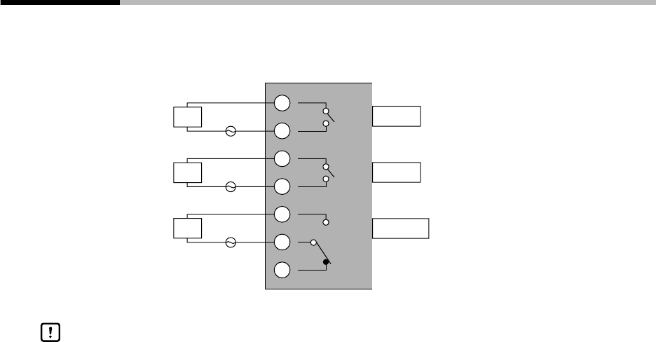
4-10 Connecting Event Output (relay output)
Event outputs EV1 and EV2 are 1a contact, and event output EV3 is 1a1b. Event outputs are connected on the
standard terminal base.
10
8
9
6
7
4
5
EV1 1a
EV2 1a
EV3 1a1b
Load
Power supply
Load
Power supply
Load
Power supply
Standard terminal base
Contact rating, resistive load
1A (30/250Vdc)
Contact rating, resistive load
1A (30/250Vdc)
Contact rating, resistive load
2A (30/250Vdc)
Minimum switching current: 10mA
When switching small currents, connect a bleeder resistor to allow current flow of
the minimum relay switching input (10mA min.).
Handling Precautions