
Clock Radio User Manual
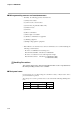
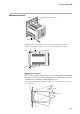
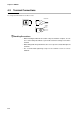
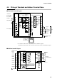
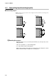
Table Of Contents
- CP-UM-5093E-04.pdf
- SAFETY PRECAUTIONS
- Contents
- Chapter 1. GENERAL
- Chapter 2. NAMES & FUNCTIONS OF PARTS
- Chapter 3. MOUNTING
- Chapter 4. WIRING
- 4-1 Wiring Precautions
- 4-2 Compensating Lead
- 4-3 Terminal Connections
- 4-4 Layout of Terminals and Recommended Lead Draw-out Direction
- 4-5 Connecting the Ground and Power Supply
- 4-6 Wiring of Standard and Add-on Terminal Base
- 4-7 Connecting Inputs (analog inputs)
- 4-8 Connecting control outputs (outputs 1, 2)
- 4-9 Connecting auxiliary outputs (outputs 2, 3)
- 4-10 Connecting Event Output (relay output)
- 4-11 Connecting Time Event Output (open-collector)
- 4-12 Connecting External Switch (RSW) Input
- 4-13 Connecting for Communications
- 4-14 Isolating Inputs and Outputs
- Chapter 5. FUNCTIONS
- Chapter 6. OPERATION
- Chapter 7. PARAMETER SETUP
- Chapter 8. PROGRAM SETUP
- Chapter 9. TROUBLESHOOTING
- Chapter 10. SPECIFICATIONS
- Chapter 11. CALIBRATION
- Index
Chapter 4. WIRING
4-3
4-2 Compensating Lead
In the case of thermocouple input, connect the bare thermocouple lead to the terminal. If the thermocouple is located
a long way from the DCP301 or the thermocouple is connected to a terminal, extend the connection using a compen-
sating lead and then connect to the terminal. Use shielded compensating leads only.
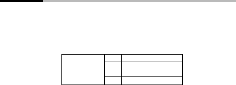
• For I/O other than thermocouples, use JCS-364 shielded instrument polyethylene insu-
lated vinyl sheath cable or equivalent product. (This is generally referred to “twisted
shielded cable for instruments.”) The following cables are recommended.
Fujikura Ltd. 2-core IPEV-S-0.9mm
2
x 1P
3-core ITEV-S-0.9mm
2
x 1T
Hitachi Cable Co. 2-core KPEV 0.9mm
2
x 1P
3-core KTEV-S-0.9mm
2
x 1T
• Shielded, multi-core microphone cord (MVVS) can be used if there is little electro-
magnetic induction.