
Clock Radio User Manual
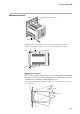
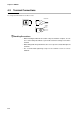
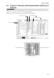
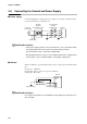
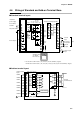
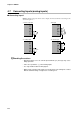
Table Of Contents
- CP-UM-5093E-04.pdf
- SAFETY PRECAUTIONS
- Contents
- Chapter 1. GENERAL
- Chapter 2. NAMES & FUNCTIONS OF PARTS
- Chapter 3. MOUNTING
- Chapter 4. WIRING
- 4-1 Wiring Precautions
- 4-2 Compensating Lead
- 4-3 Terminal Connections
- 4-4 Layout of Terminals and Recommended Lead Draw-out Direction
- 4-5 Connecting the Ground and Power Supply
- 4-6 Wiring of Standard and Add-on Terminal Base
- 4-7 Connecting Inputs (analog inputs)
- 4-8 Connecting control outputs (outputs 1, 2)
- 4-9 Connecting auxiliary outputs (outputs 2, 3)
- 4-10 Connecting Event Output (relay output)
- 4-11 Connecting Time Event Output (open-collector)
- 4-12 Connecting External Switch (RSW) Input
- 4-13 Connecting for Communications
- 4-14 Isolating Inputs and Outputs
- Chapter 5. FUNCTIONS
- Chapter 6. OPERATION
- Chapter 7. PARAMETER SETUP
- Chapter 8. PROGRAM SETUP
- Chapter 9. TROUBLESHOOTING
- Chapter 10. SPECIFICATIONS
- Chapter 11. CALIBRATION
- Index
Chapter 3. MOUNTING
3-5
Mounting bracket 81405411-001Panel
Mounting bracket
■ Mounting method
• Firmly secure the top and bottom of the controller by the mounting brackets.
• When mounting the controller, secure by lower mounting bracket (1) first.
(1)
Panel
Panel
Mounting bracket
(2)
To secure the controller, tighten the screw on the mounting bracket (supplied)
until there is no more play and then tighten a further full turn. Take care not to
overtighten the screw. Doing so might deform the case.
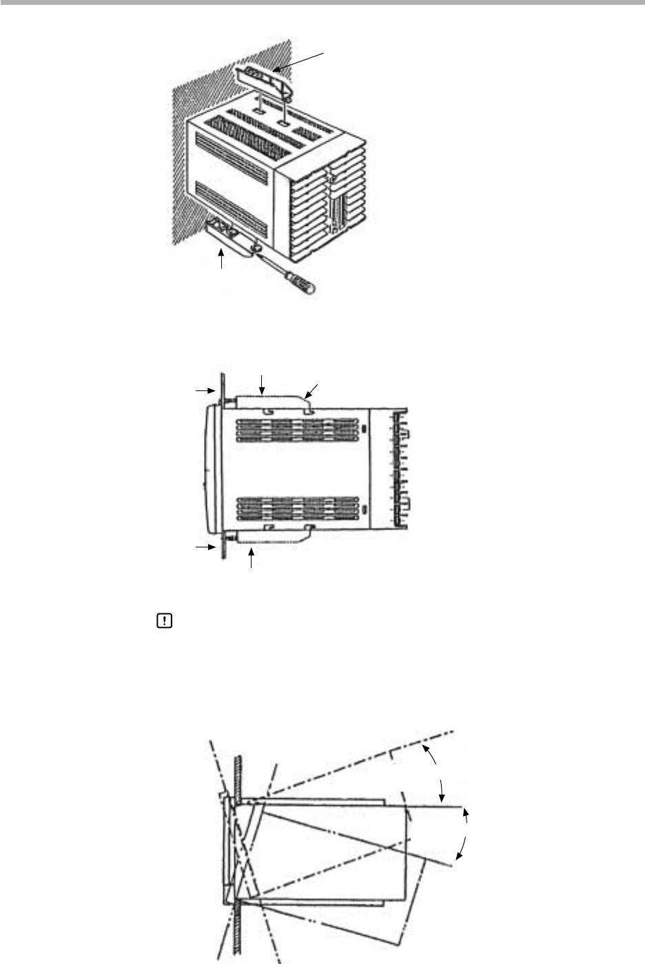
• Keep the mounting angle to within 10° from the horizontal at both the controller rear
top and bottom.
Lift up from rear by
10° max.
Pull down from rear by
10° max.
Handling Precautions