
Clock Radio User Manual
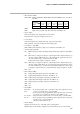

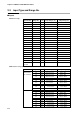
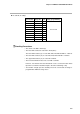
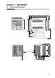
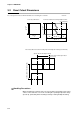
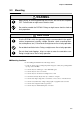
Table Of Contents
- CP-UM-5093E-04.pdf
- SAFETY PRECAUTIONS
- Contents
- Chapter 1. GENERAL
- Chapter 2. NAMES & FUNCTIONS OF PARTS
- Chapter 3. MOUNTING
- Chapter 4. WIRING
- 4-1 Wiring Precautions
- 4-2 Compensating Lead
- 4-3 Terminal Connections
- 4-4 Layout of Terminals and Recommended Lead Draw-out Direction
- 4-5 Connecting the Ground and Power Supply
- 4-6 Wiring of Standard and Add-on Terminal Base
- 4-7 Connecting Inputs (analog inputs)
- 4-8 Connecting control outputs (outputs 1, 2)
- 4-9 Connecting auxiliary outputs (outputs 2, 3)
- 4-10 Connecting Event Output (relay output)
- 4-11 Connecting Time Event Output (open-collector)
- 4-12 Connecting External Switch (RSW) Input
- 4-13 Connecting for Communications
- 4-14 Isolating Inputs and Outputs
- Chapter 5. FUNCTIONS
- Chapter 6. OPERATION
- Chapter 7. PARAMETER SETUP
- Chapter 8. PROGRAM SETUP
- Chapter 9. TROUBLESHOOTING
- Chapter 10. SPECIFICATIONS
- Chapter 11. CALIBRATION
- Index
Chapter 3. MOUNTING
3-2
92
+0.8
0
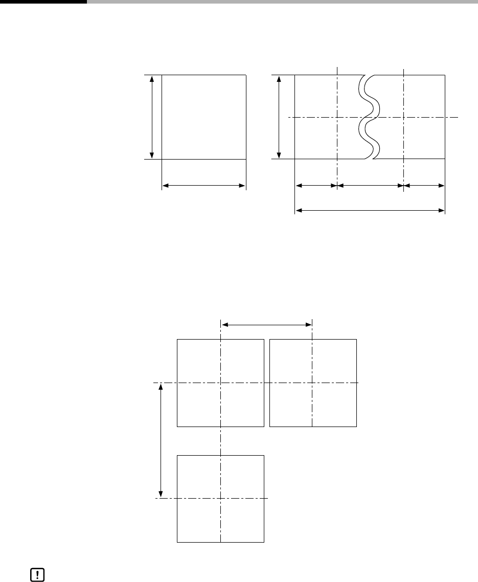
46 4696 x (N - 1)
96 x N - 4
92
+0.8
0
92
+0.8
0
N=number of units installed
Panel cutout dimensions
Panel cutout dimensions during multiple mounted
(recommended)
Unit: mm
150min.(when vertically mounted)
99 min. (when horizontally mounted)
(107 min. when hard dust-prevention
cover is used)
Panel cutout dimensions when mounting units horizontally and vertically (recommended)
3-2 Panel Cutout Dimensions
Use a steel panel of at least 2mm in thickness for mounting the controller.
When mounting the controller, take care to prevent the temperature at the lower
surface of the controller’s case from exceeding the operating temperature range
(0 to 50°C), particularly when mounting vertically or during multiple mounting.
Handling Precautions