
Clock Radio User Manual
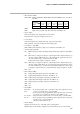

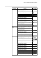
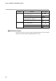
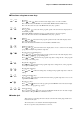
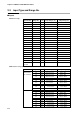
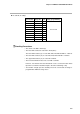
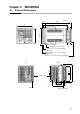
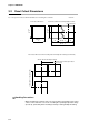
Table Of Contents
- CP-UM-5093E-04.pdf
- SAFETY PRECAUTIONS
- Contents
- Chapter 1. GENERAL
- Chapter 2. NAMES & FUNCTIONS OF PARTS
- Chapter 3. MOUNTING
- Chapter 4. WIRING
- 4-1 Wiring Precautions
- 4-2 Compensating Lead
- 4-3 Terminal Connections
- 4-4 Layout of Terminals and Recommended Lead Draw-out Direction
- 4-5 Connecting the Ground and Power Supply
- 4-6 Wiring of Standard and Add-on Terminal Base
- 4-7 Connecting Inputs (analog inputs)
- 4-8 Connecting control outputs (outputs 1, 2)
- 4-9 Connecting auxiliary outputs (outputs 2, 3)
- 4-10 Connecting Event Output (relay output)
- 4-11 Connecting Time Event Output (open-collector)
- 4-12 Connecting External Switch (RSW) Input
- 4-13 Connecting for Communications
- 4-14 Isolating Inputs and Outputs
- Chapter 5. FUNCTIONS
- Chapter 6. OPERATION
- Chapter 7. PARAMETER SETUP
- Chapter 8. PROGRAM SETUP
- Chapter 9. TROUBLESHOOTING
- Chapter 10. SPECIFICATIONS
- Chapter 11. CALIBRATION
- Index
Chapter 2. NAMES & FUNCTIONS OF PARTS
2-9
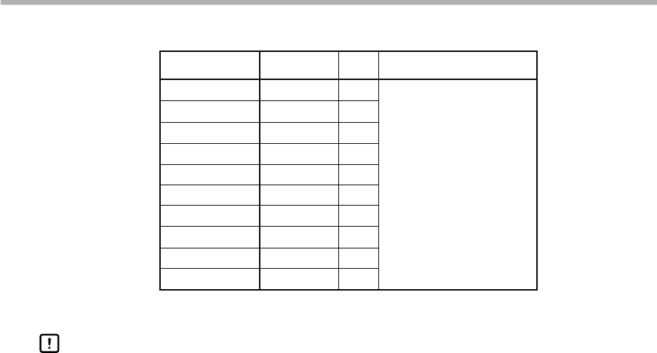
● dc current, dc voltage
Input Format Range No. Code Range (programmable)
4 to 20mA 64 C01
0 to 20mA 65 C08
0 to 10mA 66 M01
-10 to +10mV 67 L02
0 to 100mV 68 L01 -1999 to 9999
0 to 1V 69 L04
-1 to +1V 70 L08
1 to 5V 71 V01
0 to 5V 72 L05
0 to 10V 73 L07
• The unit of code Z06 is Kelvin (K)
• The lower limit readout of code B18 is 20°C (68°F).
The lower limit readout (°C) of codes K44, K46, T44, Z08 and Z07 is -199.9°C.
• The lower limit readout (°C) of codes F50, F46, P50 and P46 is -199.9°C.
• The upper limit readout (°C) of codes F01 and P01.
• The PV lower limit alarm does not occur with code F50.
However, note that the PV lower limit alarm occurs at a disconnection when
input has been downscaled when input is disconnected during setup.
• The number of digits past the decimal point for dc current and dc voltage is
programmable within the range 0 to 3.
Handling Precautions