
Clock Radio User Manual
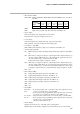

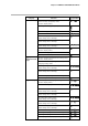
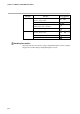
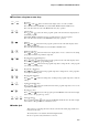
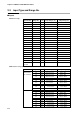
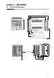
Table Of Contents
- CP-UM-5093E-04.pdf
- SAFETY PRECAUTIONS
- Contents
- Chapter 1. GENERAL
- Chapter 2. NAMES & FUNCTIONS OF PARTS
- Chapter 3. MOUNTING
- Chapter 4. WIRING
- 4-1 Wiring Precautions
- 4-2 Compensating Lead
- 4-3 Terminal Connections
- 4-4 Layout of Terminals and Recommended Lead Draw-out Direction
- 4-5 Connecting the Ground and Power Supply
- 4-6 Wiring of Standard and Add-on Terminal Base
- 4-7 Connecting Inputs (analog inputs)
- 4-8 Connecting control outputs (outputs 1, 2)
- 4-9 Connecting auxiliary outputs (outputs 2, 3)
- 4-10 Connecting Event Output (relay output)
- 4-11 Connecting Time Event Output (open-collector)
- 4-12 Connecting External Switch (RSW) Input
- 4-13 Connecting for Communications
- 4-14 Isolating Inputs and Outputs
- Chapter 5. FUNCTIONS
- Chapter 6. OPERATION
- Chapter 7. PARAMETER SETUP
- Chapter 8. PROGRAM SETUP
- Chapter 9. TROUBLESHOOTING
- Chapter 10. SPECIFICATIONS
- Chapter 11. CALIBRATION
- Index
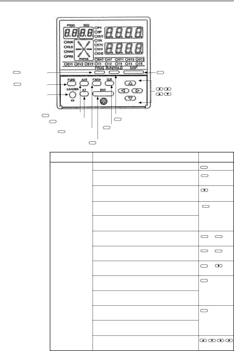
Chapter 2. NAMES & FUNCTIONS OF PARTS
2-4
FUNC
+
DISP
PROG
PROG
PROG
A/M
AT
: Program key
: Function key
Loader jack
: Auto/Manual key
: Auto-tuning key
: Parameter key
PROG
FUNC
A/M
AT
PARA
: Enter key
ENT
: Clear key
CLR
: Run/Hold key
RUN/HOLD
: Display key
DISP
: Left arrow key, right arrow key
: Up arrow key, down arrow key
To change the display
To change the program No. in ascending order
(in READY mode)
To execute running of program
(in READY mode)
To run the program
(in READY, HOLD, FAST modes)
To hold the program
(in RUN mode)
To reset the program
(in READY, HOLD, FAST, END modes)
To advance the program
(in RUN, HOLD, FAST modes)
To run the program fast
(in RUN, HOLD modes)
To execute manual operation
(in AUTO mode)
To execute automatic operation
(in MANUAL mode)
To start auto-tuning
(when not executing auto-tuning)
To cancel auto-tuning
(when executing auto-tuning)
To change values during manual operation
(when MV or SP is blinking)
+
DISP
+
RUN/HOLD
RUN/HOLD
Category Function Key operation
Basic display state
■ Keys