
Clock Radio User Manual
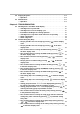
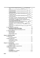
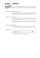
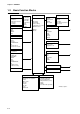
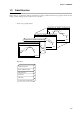
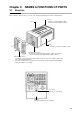
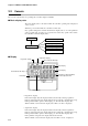
Table Of Contents
- CP-UM-5093E-04.pdf
- SAFETY PRECAUTIONS
- Contents
- Chapter 1. GENERAL
- Chapter 2. NAMES & FUNCTIONS OF PARTS
- Chapter 3. MOUNTING
- Chapter 4. WIRING
- 4-1 Wiring Precautions
- 4-2 Compensating Lead
- 4-3 Terminal Connections
- 4-4 Layout of Terminals and Recommended Lead Draw-out Direction
- 4-5 Connecting the Ground and Power Supply
- 4-6 Wiring of Standard and Add-on Terminal Base
- 4-7 Connecting Inputs (analog inputs)
- 4-8 Connecting control outputs (outputs 1, 2)
- 4-9 Connecting auxiliary outputs (outputs 2, 3)
- 4-10 Connecting Event Output (relay output)
- 4-11 Connecting Time Event Output (open-collector)
- 4-12 Connecting External Switch (RSW) Input
- 4-13 Connecting for Communications
- 4-14 Isolating Inputs and Outputs
- Chapter 5. FUNCTIONS
- Chapter 6. OPERATION
- Chapter 7. PARAMETER SETUP
- Chapter 8. PROGRAM SETUP
- Chapter 9. TROUBLESHOOTING
- Chapter 10. SPECIFICATIONS
- Chapter 11. CALIBRATION
- Index
Chapter 2. NAMES & FUNCTIONS OF PARTS
2-2
2-2 Console
The console comprises keys for operating the controller, displays and LEDs.
■ Basic display state
The “basic display state” is the state in which the controller operating state is displayed
on the console.
When the power is turned ON, the controller is in this state.
Key operation changes the controller from the basic display state to one of the parameter
setup, program setup, program copy or general reset states. Key operation also returns
the controller to the basic display state.
Parameter setups
Program setups
Program copy
General reset
Power ON
Basic display states
■ Display
Program No. display
Mode indicator LED lamps
Event LEDs
Segment No. display
Basic indicator LED lamps
Upper display
Lower display
Low battery voltage LED (BAT)
Control/output state LED
Profile display
• Program No. display
In the basic display state, this display indicates the currently selected program No.
In the program setup state, this display indicates the program No. currently being set up.
During constant-value operation, this display goes out in the basic display state.
When an alarm occurs in the basic display state, alarm code “A L” is displayed.
• Segment No. display
In the basic display state, this display indicates the currently selected segment No.
In the program setup state, this display indicates the segment No. currently being set up.
During constant-value operation, this display goes out in the basic display state.
In the parameter setup state, this display indicates the item No.
When an alarm occurs in the basic display state, the alarm code No. is displayed.