
Clock Radio User Manual
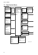
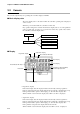
Table Of Contents
- CP-UM-5093E-04.pdf
- SAFETY PRECAUTIONS
- Contents
- Chapter 1. GENERAL
- Chapter 2. NAMES & FUNCTIONS OF PARTS
- Chapter 3. MOUNTING
- Chapter 4. WIRING
- 4-1 Wiring Precautions
- 4-2 Compensating Lead
- 4-3 Terminal Connections
- 4-4 Layout of Terminals and Recommended Lead Draw-out Direction
- 4-5 Connecting the Ground and Power Supply
- 4-6 Wiring of Standard and Add-on Terminal Base
- 4-7 Connecting Inputs (analog inputs)
- 4-8 Connecting control outputs (outputs 1, 2)
- 4-9 Connecting auxiliary outputs (outputs 2, 3)
- 4-10 Connecting Event Output (relay output)
- 4-11 Connecting Time Event Output (open-collector)
- 4-12 Connecting External Switch (RSW) Input
- 4-13 Connecting for Communications
- 4-14 Isolating Inputs and Outputs
- Chapter 5. FUNCTIONS
- Chapter 6. OPERATION
- Chapter 7. PARAMETER SETUP
- Chapter 8. PROGRAM SETUP
- Chapter 9. TROUBLESHOOTING
- Chapter 10. SPECIFICATIONS
- Chapter 11. CALIBRATION
- Index
Chapter 2. NAMES & FUNCTIONS OF PARTS
2-1
Chapter 2. NAMES & FUNCTIONS OF PARTS
2-1 Structure
This controller comprises a body, console, case, standard terminal base and add-on terminal base.
Key cover
Cover for preventing erroneous operation.
Lock screw
Fixes the case to the body.
Case
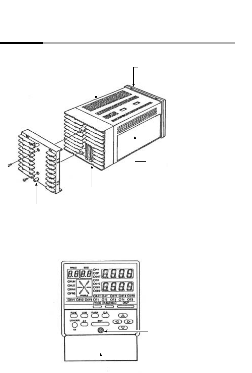
Console
Body
Contains console and electrical circuits.
Standard terminal base
Add-on terminal base
Contains 7-segment display, LEDs,
operation keys and loader connector.
Connectors for connecting power, input, output, event outputs,
external switch inputs (4) and auxiliary outputs (options)
Terminal for connecting external switch inputs (8 options), time event outputs (options) and
CPL communications (options).
The add-on terminal base is provided only on models that support optional external switch
inputs (8) and time event outputs.