
Clock Radio User Manual
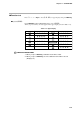
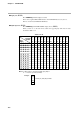
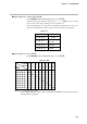
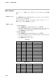
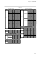
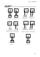
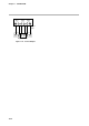
Table Of Contents
- CP-UM-5093E-04.pdf
- SAFETY PRECAUTIONS
- Contents
- Chapter 1. GENERAL
- Chapter 2. NAMES & FUNCTIONS OF PARTS
- Chapter 3. MOUNTING
- Chapter 4. WIRING
- 4-1 Wiring Precautions
- 4-2 Compensating Lead
- 4-3 Terminal Connections
- 4-4 Layout of Terminals and Recommended Lead Draw-out Direction
- 4-5 Connecting the Ground and Power Supply
- 4-6 Wiring of Standard and Add-on Terminal Base
- 4-7 Connecting Inputs (analog inputs)
- 4-8 Connecting control outputs (outputs 1, 2)
- 4-9 Connecting auxiliary outputs (outputs 2, 3)
- 4-10 Connecting Event Output (relay output)
- 4-11 Connecting Time Event Output (open-collector)
- 4-12 Connecting External Switch (RSW) Input
- 4-13 Connecting for Communications
- 4-14 Isolating Inputs and Outputs
- Chapter 5. FUNCTIONS
- Chapter 6. OPERATION
- Chapter 7. PARAMETER SETUP
- Chapter 8. PROGRAM SETUP
- Chapter 9. TROUBLESHOOTING
- Chapter 10. SPECIFICATIONS
- Chapter 11. CALIBRATION
- Index
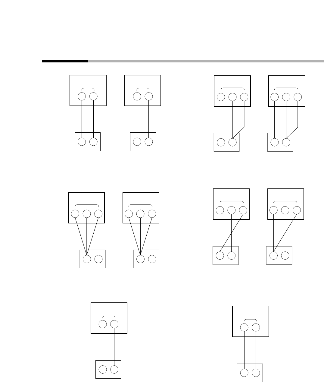
11-3 Set Up
Gain No. 0 to 7 Gain No. 16 to 17 Gain No. 9 to 10 Gain No. 19
Gain No. 11 to 12(0%) Gain No. 20(0%) Gain No. 11 to 12(100%) Gain No. 20(100%)
Gain No. 8 Gain No. 18
Millivolt sources
26 27
-
+
PV
CH2
Copper
leads
Signal generators 4–20mA
33 31
−
+
PV
CH1
Copper
leads
Copper
leads
PV
CH1
PV
CH2
34 33 32
Decade resistance box
30 29 28
Decade resistance box
Copper
leads
PV
CH1
PV
CH2
34 33 32
Decade resistance box
30 29 28
Decade resistance box
Copper
leads
PV
CH1
PV
CH2
34 33 32
Decade resistance box
30 29 28
Decade resistance box
34 33
+
−
PV
CH1
Millivolt sources
28 29
+
−
PV
CH2
Copper
leads
Millivolt sources
11-13
Chapter 11. CALIBRATION