
Clock Radio User Manual
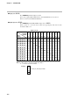
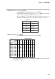
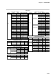
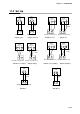
Table Of Contents
- CP-UM-5093E-04.pdf
- SAFETY PRECAUTIONS
- Contents
- Chapter 1. GENERAL
- Chapter 2. NAMES & FUNCTIONS OF PARTS
- Chapter 3. MOUNTING
- Chapter 4. WIRING
- 4-1 Wiring Precautions
- 4-2 Compensating Lead
- 4-3 Terminal Connections
- 4-4 Layout of Terminals and Recommended Lead Draw-out Direction
- 4-5 Connecting the Ground and Power Supply
- 4-6 Wiring of Standard and Add-on Terminal Base
- 4-7 Connecting Inputs (analog inputs)
- 4-8 Connecting control outputs (outputs 1, 2)
- 4-9 Connecting auxiliary outputs (outputs 2, 3)
- 4-10 Connecting Event Output (relay output)
- 4-11 Connecting Time Event Output (open-collector)
- 4-12 Connecting External Switch (RSW) Input
- 4-13 Connecting for Communications
- 4-14 Isolating Inputs and Outputs
- Chapter 5. FUNCTIONS
- Chapter 6. OPERATION
- Chapter 7. PARAMETER SETUP
- Chapter 8. PROGRAM SETUP
- Chapter 9. TROUBLESHOOTING
- Chapter 10. SPECIFICATIONS
- Chapter 11. CALIBRATION
- Index
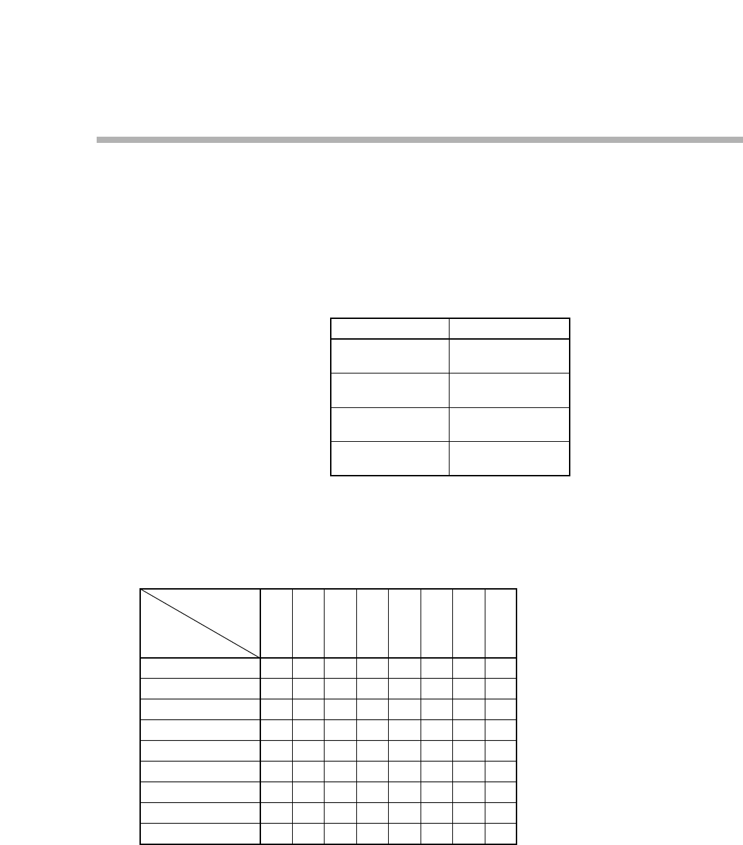
●Digital output test for control output (
00-04
)
Press PARA key until the PROG/SEG display shows (
00-04
).
When the digit of upper display is changed by ↑, ↓, ←, or → keys, the state of voltage
pulse or relay control output is changed as shown in Table 11-5.
Since the 6D hardware is of voltage pulse output (0D and 2G hardware is of relay) spec-
ification, the ON/OFF check must be performed in meeting with the specification.
Table 11-5.
●Digital output test for event (
00-05
)
Press PARA key until the PROG/SEG display shows (
00-05
).
Table 11-6. DO
0.0.0.0.
0.0.0.1.
0.0.0.2.
0.0.0.4.
0.0.0.8.
0.0.1.0.
0.0.2.0.
0.0.4.0.
0.0.8.0.
—
ON
—
—
—
—
—
—
—
DO
Terminal
Number
Upper
Display
Notes: 1. “—” in the table means “OFF”.
2. Since the DO hardware is of open collector specification, the ON/OFF check must be performed in
meeting with the specification.
(4)
(5)
(6)
(7)
—
—
ON
—
—
—
—
—
—
(8)
(9)
—
—
—
ON
—
—
—
—
—
(49)
(55)
—
—
—
—
ON
—
—
—
—
(50)
(55)
—
—
—
—
—
ON
—
—
—
(51)
(55)
—
—
—
—
—
—
ON
—
—
(52)
(55)
—
—
—
—
—
—
—
ON
—
(53)
(55)
—
—
—
—
—
—
—
—
ON
↔
↔
↔
↔
↔
↔
↔
↔
0.0.0.0.
0.0.0.1.
0.0.0.2.
0.0.0.4.
Upper Display State
All OFF
6D, 0D, 2G output
CH1 ON
6D, 2G output
CH2 ON
6D output
CH3 ON
11-9
Chapter 11. CALIBRATION