
Clock Radio User Manual
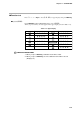
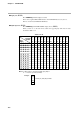
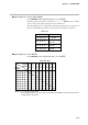
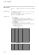
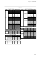
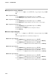
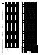
Table Of Contents
- CP-UM-5093E-04.pdf
- SAFETY PRECAUTIONS
- Contents
- Chapter 1. GENERAL
- Chapter 2. NAMES & FUNCTIONS OF PARTS
- Chapter 3. MOUNTING
- Chapter 4. WIRING
- 4-1 Wiring Precautions
- 4-2 Compensating Lead
- 4-3 Terminal Connections
- 4-4 Layout of Terminals and Recommended Lead Draw-out Direction
- 4-5 Connecting the Ground and Power Supply
- 4-6 Wiring of Standard and Add-on Terminal Base
- 4-7 Connecting Inputs (analog inputs)
- 4-8 Connecting control outputs (outputs 1, 2)
- 4-9 Connecting auxiliary outputs (outputs 2, 3)
- 4-10 Connecting Event Output (relay output)
- 4-11 Connecting Time Event Output (open-collector)
- 4-12 Connecting External Switch (RSW) Input
- 4-13 Connecting for Communications
- 4-14 Isolating Inputs and Outputs
- Chapter 5. FUNCTIONS
- Chapter 6. OPERATION
- Chapter 7. PARAMETER SETUP
- Chapter 8. PROGRAM SETUP
- Chapter 9. TROUBLESHOOTING
- Chapter 10. SPECIFICATIONS
- Chapter 11. CALIBRATION
- Index
●Display test (
00-02
)
Press PARA key until the display test starts.
Then, each 7-segment LED, LED indicators and LCD illuminates at every 0.5 sec.
This is to check if each LED/LCD illuminates.
●Digital input test (
00-03
)
Press PARA key until the PROG/SEG display shows (
00-03
).
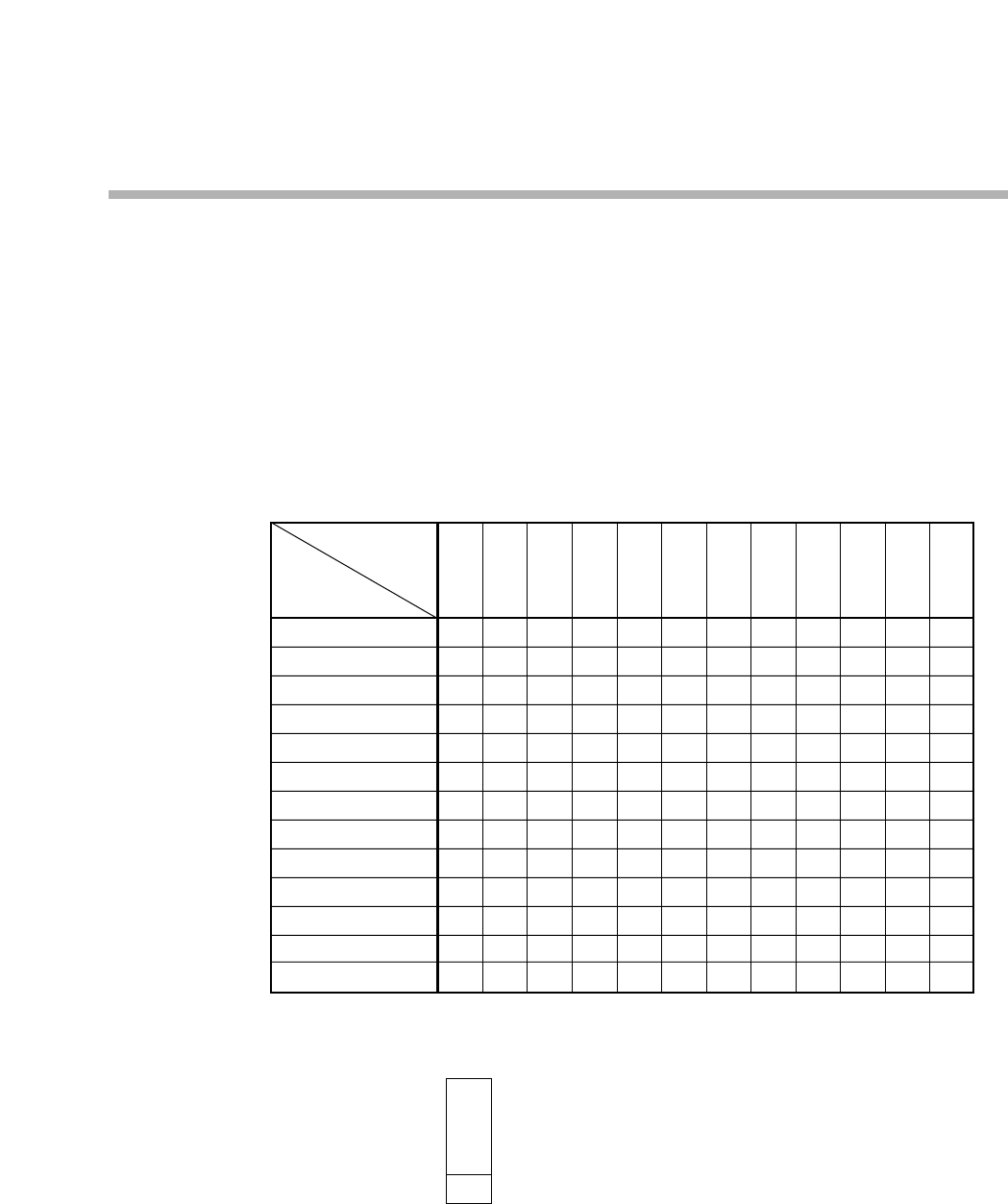
When you turn on or off each remote switch, the upper display will show the data
described in Table 11-4.
Table 11-4. DI
0.0.0.0.
0.0.0.1.
0.0.0.2.
0.0.0.4.
0.0.0.8.
0.0.1.0.
0.0.2.0.
0.0.4.0.
0.0.8.0.
0.1.0.0.
0.2.0.0.
0.4.0.0.
0.8.0.0.
—
ON
—
—
—
—
—
—
—
—
—
—
—
DI
Terminal
Number
Upper
Display
Notes: 1. “ON” means to short the terminals by a jumper.
2. “—” means to open the terminals.
Example:
(21)
(25)
(22)
(25)
—
—
ON
—
—
—
—
—
—
—
—
—
—
(23)
(25)
—
—
—
ON
—
—
—
—
—
—
—
—
—
(24)
(25)
—
—
—
—
ON
—
—
—
—
—
—
—
—
(41)
(25)
—
—
—
—
—
ON
—
—
—
—
—
—
—
(42)
(25)
—
—
—
—
—
—
ON
—
—
—
—
—
—
(43)
(25)
—
—
—
—
—
—
—
ON
—
—
—
—
—
(44)
(25)
—
—
—
—
—
—
—
—
ON
—
—
—
—
(45)
(25)
—
—
—
—
—
—
—
—
—
ON
—
—
—
(46)
(25)
—
—
—
—
—
—
—
—
—
—
ON
—
—
(47)
(25)
—
—
—
—
—
—
—
—
—
—
—
ON
—
(48)
(25)
—
—
—
—
—
—
—
—
—
—
—
—
ON
(21)
(25)
ON
= Short (21) and (25) terminals.
↔
↔
↔
↔
↔
↔
↔
↔
↔
↔
↔
↔
↔
11-8
Chapter 11. CALIBRATION