
Clock Radio User Manual
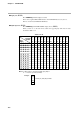
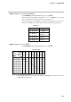
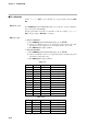
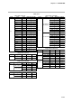
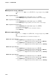
Table Of Contents
- CP-UM-5093E-04.pdf
- SAFETY PRECAUTIONS
- Contents
- Chapter 1. GENERAL
- Chapter 2. NAMES & FUNCTIONS OF PARTS
- Chapter 3. MOUNTING
- Chapter 4. WIRING
- 4-1 Wiring Precautions
- 4-2 Compensating Lead
- 4-3 Terminal Connections
- 4-4 Layout of Terminals and Recommended Lead Draw-out Direction
- 4-5 Connecting the Ground and Power Supply
- 4-6 Wiring of Standard and Add-on Terminal Base
- 4-7 Connecting Inputs (analog inputs)
- 4-8 Connecting control outputs (outputs 1, 2)
- 4-9 Connecting auxiliary outputs (outputs 2, 3)
- 4-10 Connecting Event Output (relay output)
- 4-11 Connecting Time Event Output (open-collector)
- 4-12 Connecting External Switch (RSW) Input
- 4-13 Connecting for Communications
- 4-14 Isolating Inputs and Outputs
- Chapter 5. FUNCTIONS
- Chapter 6. OPERATION
- Chapter 7. PARAMETER SETUP
- Chapter 8. PROGRAM SETUP
- Chapter 9. TROUBLESHOOTING
- Chapter 10. SPECIFICATIONS
- Chapter 11. CALIBRATION
- Index
■ Function test
Press ↑, ↓, ←, or → keys to show (
0.0.0.0
) on upper display, then press ENT key.
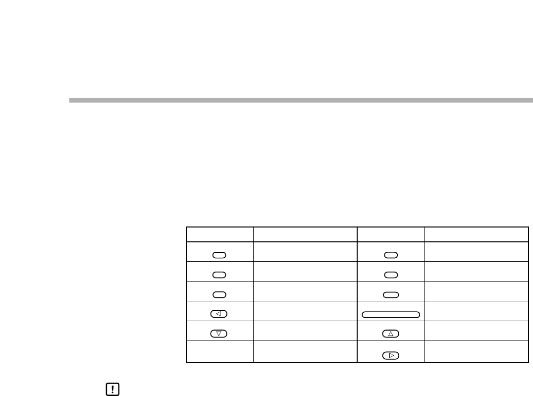
●Key test (
00-01
)
Press PARA key until the PROG/SEG display shows (
00-01
).
When you press each key, the data appears in the upper display (shown in Table 11-3).
Table 11-3. Upper Display
HANDLING PRECAUTIONS
1. When you press DISP key, calibration mode will be exited.
2. When you press PARA key, the next calibration menu will be entered
(Display test).
0.0.4.0.
0.0.2.0.
0.0.0.4.
0.0.0.8.
0.8.0.0.
Key Data
4.0.0.0.
0.0.0.1.
0.1.0.0.
0.2.0.0.
0.0.1.0.
1.0.0.0.
Key Data
PROG
CLR
RUN/HOLD
A/M
FUNC
AT
ENT
11-7
Chapter 11. CALIBRATION