
Clock Radio User Manual
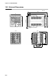
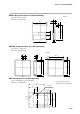
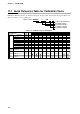
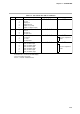
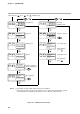
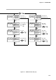
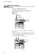
Table Of Contents
- CP-UM-5093E-04.pdf
- SAFETY PRECAUTIONS
- Contents
- Chapter 1. GENERAL
- Chapter 2. NAMES & FUNCTIONS OF PARTS
- Chapter 3. MOUNTING
- Chapter 4. WIRING
- 4-1 Wiring Precautions
- 4-2 Compensating Lead
- 4-3 Terminal Connections
- 4-4 Layout of Terminals and Recommended Lead Draw-out Direction
- 4-5 Connecting the Ground and Power Supply
- 4-6 Wiring of Standard and Add-on Terminal Base
- 4-7 Connecting Inputs (analog inputs)
- 4-8 Connecting control outputs (outputs 1, 2)
- 4-9 Connecting auxiliary outputs (outputs 2, 3)
- 4-10 Connecting Event Output (relay output)
- 4-11 Connecting Time Event Output (open-collector)
- 4-12 Connecting External Switch (RSW) Input
- 4-13 Connecting for Communications
- 4-14 Isolating Inputs and Outputs
- Chapter 5. FUNCTIONS
- Chapter 6. OPERATION
- Chapter 7. PARAMETER SETUP
- Chapter 8. PROGRAM SETUP
- Chapter 9. TROUBLESHOOTING
- Chapter 10. SPECIFICATIONS
- Chapter 11. CALIBRATION
- Index
11-2 Calibration Procedures
■ Enter calibration mode
(1) Release keylock. (PARA
LoC=0
and
PrtC=0
)
(2) Press DISP key to permit ordinary indication condition.
Change to READY (RUN and HLD are off) and AUTO (MAN off) modes.
The following LEDs will illuminate after the above operations.
RUN LED is OFF
HLD LED is OFF
MAN LED is OFF
Figure 11-2.
(3) To enter calibration mode, hold down the FUNC key, and press ENT key and ↓
key simultaneously.
The display will show the symbols described in Figure 11-3. If the indication is dif-
ferent, repeat the above procedure after pushing DISP key to refresh the display.
(4) To select individual calibration items, press ↑, ↓, ←, or → keys to select the item
by scrolling, then PARA key, and ENT key.
The order of calibration items is described in Table 11-2.
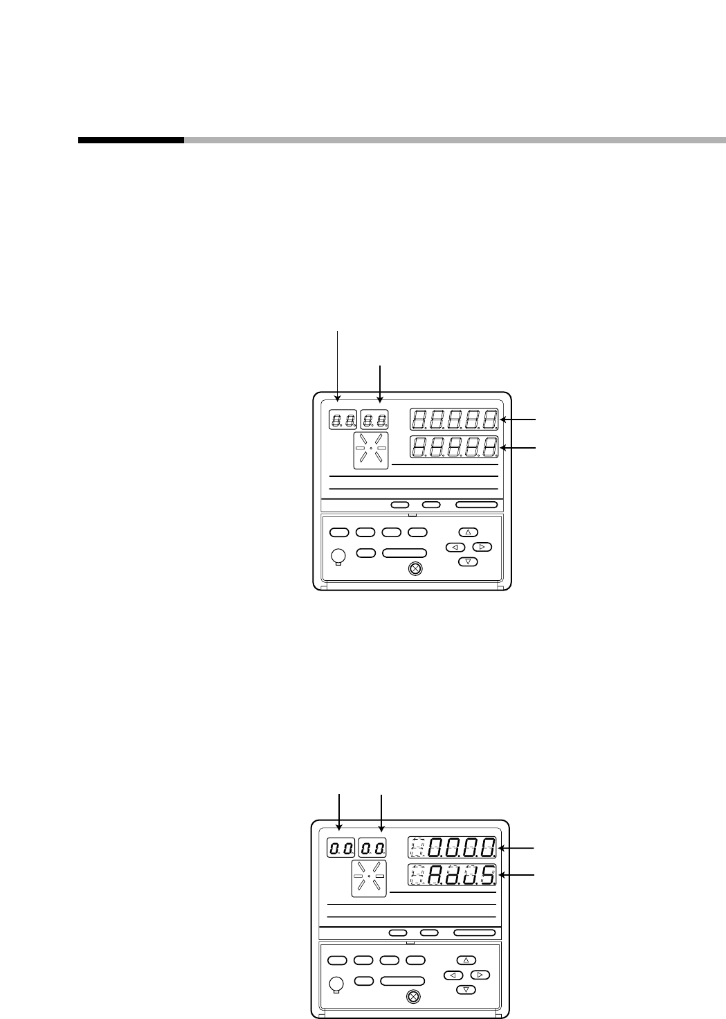
Figure 11-3.
0.0.0.0.
A.d.J.S.
00
00
AT ENT
FUNC A/M
PARA CLR
LOADER
PROG
RUN/HOLD DISP
❍RUN
❍HLD
❍MAN
❍PRG
PROFILE
PROG SEG
❍PV
❍SP
❍OUT
❍TM
❍CYC
❍CH1
❍CH2
❍BAT ❍AT ❍OT1 ❍OT2 ❍OT3
❍EV1 ❍EV2 ❍EV3 ❍T1 ❍T2 ❍T3 ❍T4 ❍T5
Upper Display
Lower Display
PROG Display
(Program No. Display)
SEG Display
(Segment No. Display)
AT ENT
FUNC A/M
PARA CLR
LOADER
PROG
RUN/HOLD DISP
❍RUN
❍HLD
❍MAN
❍PRG
PROFILE
PROG SEG
❍PV
❍SP
❍OUT
❍TM
❍CYC
❍CH1
❍CH2
❍BAT ❍AT ❍OT1 ❍OT2 ❍OT3
❍EV1 ❍EV2 ❍EV3 ❍T1 ❍T2 ❍T3 ❍T4 ❍T5
11-6
Chapter 11. CALIBRATION