
Clock Radio User Manual
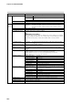
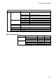
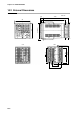
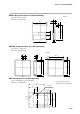
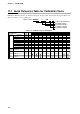
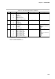
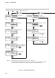
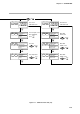
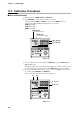
Table Of Contents
- CP-UM-5093E-04.pdf
- SAFETY PRECAUTIONS
- Contents
- Chapter 1. GENERAL
- Chapter 2. NAMES & FUNCTIONS OF PARTS
- Chapter 3. MOUNTING
- Chapter 4. WIRING
- 4-1 Wiring Precautions
- 4-2 Compensating Lead
- 4-3 Terminal Connections
- 4-4 Layout of Terminals and Recommended Lead Draw-out Direction
- 4-5 Connecting the Ground and Power Supply
- 4-6 Wiring of Standard and Add-on Terminal Base
- 4-7 Connecting Inputs (analog inputs)
- 4-8 Connecting control outputs (outputs 1, 2)
- 4-9 Connecting auxiliary outputs (outputs 2, 3)
- 4-10 Connecting Event Output (relay output)
- 4-11 Connecting Time Event Output (open-collector)
- 4-12 Connecting External Switch (RSW) Input
- 4-13 Connecting for Communications
- 4-14 Isolating Inputs and Outputs
- Chapter 5. FUNCTIONS
- Chapter 6. OPERATION
- Chapter 7. PARAMETER SETUP
- Chapter 8. PROGRAM SETUP
- Chapter 9. TROUBLESHOOTING
- Chapter 10. SPECIFICATIONS
- Chapter 11. CALIBRATION
- Index
Chapter 11. CALIBRATION
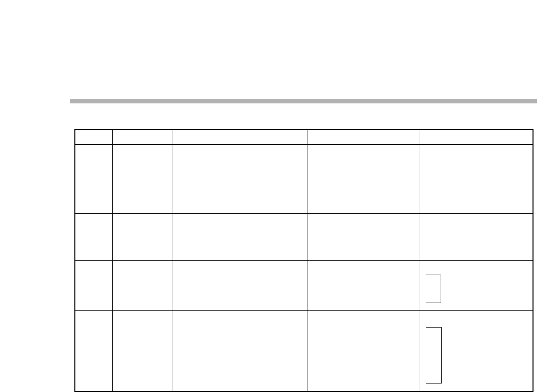
Table 11-2. Item and Sub Item Table for Calibration
0.0.0.0.
etc.
1.0.1.1.
2.0.2.2.
4.0.4.4.
AdJS
AdJS
Upper Display Shows
Lower Display ShowsDescription
Item change code
Key test
Display test
Digital input test
Output test (control)
Output test (digital output)
Item change code
Gain No.
PV input 0%
PV input 100%
Item change code
CJ input 0%
CJ count
CJ temperature
Item change code
OUT ch1 4mA output
OUT ch1 20mA output
OUT ch2 4mA output
OUT ch2 20mA output
OUT ch3 4mA output
OUT ch3 20mA output
0
1
0
1
2
3
4
5
0
1
2
3
20
1
2
3
40
1
2
3
4
5
6
Item Sub Item
Notes: 1. Items No. is shown on the PROG display.
2. Sub item No. is shown on the SEG display.
3. Item 0: Function check item
4. Items 1, 2 and 6 : Calibration items
Previous adjustment
value
AdJS
Previous adjustment
value
11-3