
Clock Radio User Manual
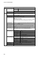
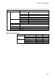
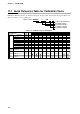
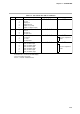
Table Of Contents
- CP-UM-5093E-04.pdf
- SAFETY PRECAUTIONS
- Contents
- Chapter 1. GENERAL
- Chapter 2. NAMES & FUNCTIONS OF PARTS
- Chapter 3. MOUNTING
- Chapter 4. WIRING
- 4-1 Wiring Precautions
- 4-2 Compensating Lead
- 4-3 Terminal Connections
- 4-4 Layout of Terminals and Recommended Lead Draw-out Direction
- 4-5 Connecting the Ground and Power Supply
- 4-6 Wiring of Standard and Add-on Terminal Base
- 4-7 Connecting Inputs (analog inputs)
- 4-8 Connecting control outputs (outputs 1, 2)
- 4-9 Connecting auxiliary outputs (outputs 2, 3)
- 4-10 Connecting Event Output (relay output)
- 4-11 Connecting Time Event Output (open-collector)
- 4-12 Connecting External Switch (RSW) Input
- 4-13 Connecting for Communications
- 4-14 Isolating Inputs and Outputs
- Chapter 5. FUNCTIONS
- Chapter 6. OPERATION
- Chapter 7. PARAMETER SETUP
- Chapter 8. PROGRAM SETUP
- Chapter 9. TROUBLESHOOTING
- Chapter 10. SPECIFICATIONS
- Chapter 11. CALIBRATION
- Index
Chapter 11. CALIBRATION
11-1 Quick Reference Table for Calibration Items
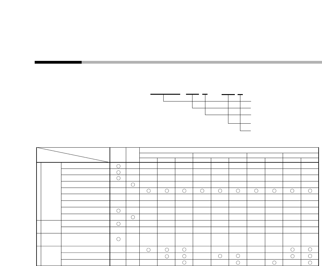
DCP301 and DCP302 controllers are numbered using the following format. Format items may require different cal-
ibration procedures, as shown in Table 11-1.
Table 11-1. Calibration Items for Each Model
Calibration
& Test Item
Function
Test
Key Test
Indicator Test
DI Test(1 to 4)
DI Test(5 to 12)
DO
Control Output Ch1 Test
DO
Control Output Ch2 Test
DO
Control Output Ch3 Test
DO
Test
(1 to 3:Event)
DO
Test
(4 to 8:Time Event)
Gain No.0 to 12
Gain No.16 to 20
Output Ch1
Output Ch2
Output Ch3
0
PV Input
Calibration
1
CJ Sensor
Calibration
2
Current
Output
Calibration
4
Option2:
1, 2
Basic
Model:
DCP301
Model
Output and Option Model Number
Output:5G, 6D Output:0D Output:2G, 3D Output:5K
Option1:00 Option1:01 Option1:02 Option1:00 Option1:01 Option1:02 Option1:00 Option1:01 Option1:00 Option1:01
(1) Basic Model Number
(2) Output Number
(3) PV Input Number
(4) Option1 Number
(5) Option2 Number
Model number:
DCP30 * * * * ES * *
*
11-2