
Clock Radio User Manual
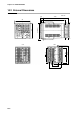
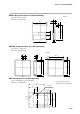
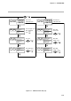
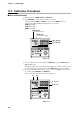
Table Of Contents
- CP-UM-5093E-04.pdf
- SAFETY PRECAUTIONS
- Contents
- Chapter 1. GENERAL
- Chapter 2. NAMES & FUNCTIONS OF PARTS
- Chapter 3. MOUNTING
- Chapter 4. WIRING
- 4-1 Wiring Precautions
- 4-2 Compensating Lead
- 4-3 Terminal Connections
- 4-4 Layout of Terminals and Recommended Lead Draw-out Direction
- 4-5 Connecting the Ground and Power Supply
- 4-6 Wiring of Standard and Add-on Terminal Base
- 4-7 Connecting Inputs (analog inputs)
- 4-8 Connecting control outputs (outputs 1, 2)
- 4-9 Connecting auxiliary outputs (outputs 2, 3)
- 4-10 Connecting Event Output (relay output)
- 4-11 Connecting Time Event Output (open-collector)
- 4-12 Connecting External Switch (RSW) Input
- 4-13 Connecting for Communications
- 4-14 Isolating Inputs and Outputs
- Chapter 5. FUNCTIONS
- Chapter 6. OPERATION
- Chapter 7. PARAMETER SETUP
- Chapter 8. PROGRAM SETUP
- Chapter 9. TROUBLESHOOTING
- Chapter 10. SPECIFICATIONS
- Chapter 11. CALIBRATION
- Index
Chapter 10. SPECIFICATIONS
10-9
■ Hard dust-proof cover set (sold separately)
(transparent polycarbonate)
Model No.: 81446083-001
8
16
4
6
1.1
(96.8)
106
4.7
96.6
106
4.7
96.6
106
Packing
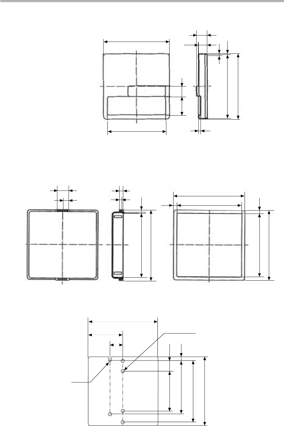
■ Terminal cover set (sold separately)
(gray non-flammable, heat-resistant PVC)
Model No.: 81446084-001
5.5
13.7
51.6
69.6
79
90
90
17
45
R1.8
5-3.6 hole
Can be attached to either of
standard or add-on terminal base.
■ Soft dust-proof cover set (sold separately)
(transparent silicon rubber)
Model No.: 81446087-001
98
86
27.5 16
12.5
15.5
2.7
3.2
1.595
98
Unit: mm