
Clock Radio User Manual
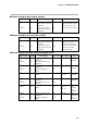
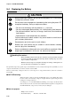
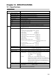
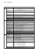
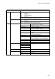
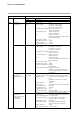
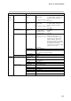
Table Of Contents
- CP-UM-5093E-04.pdf
- SAFETY PRECAUTIONS
- Contents
- Chapter 1. GENERAL
- Chapter 2. NAMES & FUNCTIONS OF PARTS
- Chapter 3. MOUNTING
- Chapter 4. WIRING
- 4-1 Wiring Precautions
- 4-2 Compensating Lead
- 4-3 Terminal Connections
- 4-4 Layout of Terminals and Recommended Lead Draw-out Direction
- 4-5 Connecting the Ground and Power Supply
- 4-6 Wiring of Standard and Add-on Terminal Base
- 4-7 Connecting Inputs (analog inputs)
- 4-8 Connecting control outputs (outputs 1, 2)
- 4-9 Connecting auxiliary outputs (outputs 2, 3)
- 4-10 Connecting Event Output (relay output)
- 4-11 Connecting Time Event Output (open-collector)
- 4-12 Connecting External Switch (RSW) Input
- 4-13 Connecting for Communications
- 4-14 Isolating Inputs and Outputs
- Chapter 5. FUNCTIONS
- Chapter 6. OPERATION
- Chapter 7. PARAMETER SETUP
- Chapter 8. PROGRAM SETUP
- Chapter 9. TROUBLESHOOTING
- Chapter 10. SPECIFICATIONS
- Chapter 11. CALIBRATION
- Index

Chapter 10. SPECIFICATIONS
10-4
PV, SP, deviation, MV, MFB
Supported
1/10000
Contact type: 1a1b
Contact rating: 5A (30Vdc, resistive load)
5A (120Vac, resistive load)
4A (240Vdc, resistive load)
Allowable contact voltage:250Vac, resistive load
125Vdc, resistive load
Max. switching power: 150W, resistive load
960VA, resistive load
Life: 100,000 operations
(resistive load at contact rating, frequency:
30 operations/minute)
Min. switching voltage: 5V
Min. switching current: 100mA
Output resolution: 1/1000
Time-proportional cycle: 5 to 120s
Contact type: 1a (2 circuits)
Contact rating: 2.5A (30Vdc, L/R=0.7ms)
4A (120Vac, cosø=0.4)
2A (240Vac, cosø=0.4)
Allowable contact voltage:250Vac, cosø=0.4
125Vdc, L/R=0.7ms
Max. switching power: 75W (L/R=0.7ms)
480VA (cosø=0.4)
Life: 100,000 operations
(cosø=0.4 at contact rating, frequency: 30
operations/minute)
Min. switching voltage: 5V
Min. switching current: 100mA
MFB (motor feedback) input range:
100 to 2500Ω
Control at MFB (motor feedback) disconnection:
ON/OFF for continuation of operation
according to MFB estimated position can
be selected.
Output current: 4 to 20/0 to 20mAdc
Allowable load resistance:600Ω max. (under operating conditions)
Output accuracy: ±0.1%FS max. (under standard condi-
tions)
±0.5%FS at output 5% or less of 0 to
20mA output
Output resolution: 1/10000
Inrush current: 25mA max. for 50ms max. (at 250Ω load)
Max. output current: 22.0mAdc
Min. output current: 0.0mAdc
Output updating cycle: 0.1s
Open terminal voltage: 25V max. (output 1)
18V max. (output 2, auxiliary outputs 1, 2)
Allowable load resistance:600Ω max. (under operating conditions)
Inrush current: 25mA max. for 50ms max. (at 250Ω load)
Load current adjustment: 2 to 22mA variable
Open terminal voltage: 25V max. (output 2 of 5K output)
18V max. (output 2 of 5K output)
OFF leakage current: 100µA max.
Output response time: At ON-OFF 600Ω load: 0.5ms max.
At OFF-ON 600Ω load: 1.0ms max.
Output resolution: 1/1000
Time-proportional cycle: 1 to 60s variable
Item Specification
Control
Output
Auxiliary output
0D output 1
3D outputs 1, 2
2G output 1
5G output 1
5K outputs 1, 2
Auxiliary outputs 1, 2
6D output 1
5K outputs 1, 2
(when current output
is switched to
voltage output)
Type
Scaling
Output resolution
Relay contact
output
M/M drive relay
Current output
(4 to 20mA)
Voltage output