
Clock Radio User Manual
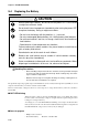
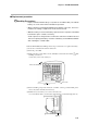
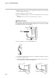
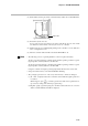
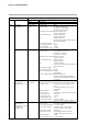
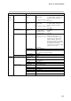
Table Of Contents
- CP-UM-5093E-04.pdf
- SAFETY PRECAUTIONS
- Contents
- Chapter 1. GENERAL
- Chapter 2. NAMES & FUNCTIONS OF PARTS
- Chapter 3. MOUNTING
- Chapter 4. WIRING
- 4-1 Wiring Precautions
- 4-2 Compensating Lead
- 4-3 Terminal Connections
- 4-4 Layout of Terminals and Recommended Lead Draw-out Direction
- 4-5 Connecting the Ground and Power Supply
- 4-6 Wiring of Standard and Add-on Terminal Base
- 4-7 Connecting Inputs (analog inputs)
- 4-8 Connecting control outputs (outputs 1, 2)
- 4-9 Connecting auxiliary outputs (outputs 2, 3)
- 4-10 Connecting Event Output (relay output)
- 4-11 Connecting Time Event Output (open-collector)
- 4-12 Connecting External Switch (RSW) Input
- 4-13 Connecting for Communications
- 4-14 Isolating Inputs and Outputs
- Chapter 5. FUNCTIONS
- Chapter 6. OPERATION
- Chapter 7. PARAMETER SETUP
- Chapter 8. PROGRAM SETUP
- Chapter 9. TROUBLESHOOTING
- Chapter 10. SPECIFICATIONS
- Chapter 11. CALIBRATION
- Index

Chapter 9. TROUBLESHOOTING
9-12
Connector
(6) Place the body on its save on a desk or flat surface so that the side on which the
battery is installed is facing up.
(7) Remove the battery from its gray holder.
(8) Remove the RAM board (approx. 3cm x 8cm) with the battery still connected to the
board.
The RAM board is connected to the base board by two connectors.
When placing the RAM board on the desk, make sure that the solder surface of
the board is face down. If the component mounting surface is placed face down,
the components may become damaged.
Connector
Connector
RAM board
(approx. 3cm x 8cm)
(9) Remove the battery connector from the RAM board.
(
10
) Connect the connector of the new battery to the RAM board making sure that it is
inserted the correct direction.
(
11
) Mount the RAM Board making sure that it is mounted in the correct direction. Do
not insert the battery cable under the RAM board.
OK No good
Handling Precautions