
Clock Radio User Manual
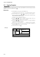
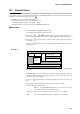
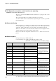
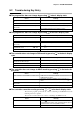
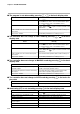
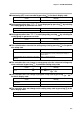
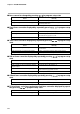
Table Of Contents
- CP-UM-5093E-04.pdf
- SAFETY PRECAUTIONS
- Contents
- Chapter 1. GENERAL
- Chapter 2. NAMES & FUNCTIONS OF PARTS
- Chapter 3. MOUNTING
- Chapter 4. WIRING
- 4-1 Wiring Precautions
- 4-2 Compensating Lead
- 4-3 Terminal Connections
- 4-4 Layout of Terminals and Recommended Lead Draw-out Direction
- 4-5 Connecting the Ground and Power Supply
- 4-6 Wiring of Standard and Add-on Terminal Base
- 4-7 Connecting Inputs (analog inputs)
- 4-8 Connecting control outputs (outputs 1, 2)
- 4-9 Connecting auxiliary outputs (outputs 2, 3)
- 4-10 Connecting Event Output (relay output)
- 4-11 Connecting Time Event Output (open-collector)
- 4-12 Connecting External Switch (RSW) Input
- 4-13 Connecting for Communications
- 4-14 Isolating Inputs and Outputs
- Chapter 5. FUNCTIONS
- Chapter 6. OPERATION
- Chapter 7. PARAMETER SETUP
- Chapter 8. PROGRAM SETUP
- Chapter 9. TROUBLESHOOTING
- Chapter 10. SPECIFICATIONS
- Chapter 11. CALIBRATION
- Index
Chapter 9. TROUBLESHOOTING
9-8
9-3 Motor Adjustment is Impossible
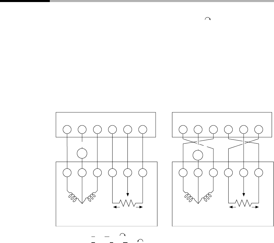
There are two ways of wiring a motor to the DCP301: wiring for direct motor rotation and wiring for reverse motor
rotation. When wired for direct motor rotation, the motor rotates in clockwise (CW ) direction when DCP301
output increases. There are two ways of making the motor rotate in the reverse direction (counterclockwise: CCW)
depending on your control requirements (e.g. cooling control):
• By switching the control operating direction on the DCP301 with the motor wired to the DCP301 for direct
motor rotation as it is, or
• By wiring the motor to the DCP301 for reverse motor rotation.
The control operating direction (direct/reverse) can be switched on this controller. If the motor is wired to the control-
ler for direct motor rotation, the DCP301 can be easily set up for control in either direction. This makes it easier to
remedy trouble that may occur during controller operation. For this reason, we recommend wiring the motor to the
DCP301 for direct motor operation.
CW: Clock Wise ( )
CCW: Counter Clock Wise ( )
The DCP301 is also provided with a function (A L 1 0 to A L 1 2) for detecting MFB disconnection or short-circuit if
the motor has been wired to the controller in the wrong way.
By this function, the DCP301 judges reverse direction wiring in the same way as direct direction wiring, and does not
generate an alarm. If the setting of variable parameter M .-C is left at the factory setting (“0”), motor operation is
continued.
The following tables summarize the phenomena that occur according to how the motor and DCP301 are wired when
the motor is automatically adjusted (variable parameter M .-A T setting 1 is input). Motor rotation is started from the
fully closed position (motor is turned as far as possible CCW).
The values displayed in the lower display in the tables are only examples. Alarms are displayed after the motor fully
closes or fully opens.
11 12 13 14 15 16
2 3 1 Y T G
14 16
Y G
~
CCW
closed
CW
open
CCW closedCW open
CCW
closed
CW
open
CCW
closed
CW
open
Wiring for direct motor rotation
DCP301
Wiring for reverse motor rotation
DCP301
MotorMotor
15
T
24Vac
24Vac
2 3
~
11 1312
1