
Clock Radio User Manual
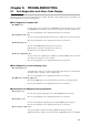
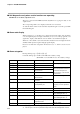
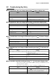
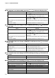
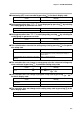
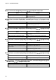
Table Of Contents
- CP-UM-5093E-04.pdf
- SAFETY PRECAUTIONS
- Contents
- Chapter 1. GENERAL
- Chapter 2. NAMES & FUNCTIONS OF PARTS
- Chapter 3. MOUNTING
- Chapter 4. WIRING
- 4-1 Wiring Precautions
- 4-2 Compensating Lead
- 4-3 Terminal Connections
- 4-4 Layout of Terminals and Recommended Lead Draw-out Direction
- 4-5 Connecting the Ground and Power Supply
- 4-6 Wiring of Standard and Add-on Terminal Base
- 4-7 Connecting Inputs (analog inputs)
- 4-8 Connecting control outputs (outputs 1, 2)
- 4-9 Connecting auxiliary outputs (outputs 2, 3)
- 4-10 Connecting Event Output (relay output)
- 4-11 Connecting Time Event Output (open-collector)
- 4-12 Connecting External Switch (RSW) Input
- 4-13 Connecting for Communications
- 4-14 Isolating Inputs and Outputs
- Chapter 5. FUNCTIONS
- Chapter 6. OPERATION
- Chapter 7. PARAMETER SETUP
- Chapter 8. PROGRAM SETUP
- Chapter 9. TROUBLESHOOTING
- Chapter 10. SPECIFICATIONS
- Chapter 11. CALIBRATION
- Index
Chapter 9. TROUBLESHOOTING
9-4
Press
RUN/HOLD
to set the controller to the RUN mode. (The
controller can be reset in case of external switch input
or communications even in the READY mode.)
Press
PROG
+
RUN/HOLD
to set the controller to the READY
mode, and press
RUN/HOLD
again to set the controller to the
RUN mode.
Set constant-value operation data M .O D E setting to 0.
Set variable parameter
L O C setting to 0 to 2.
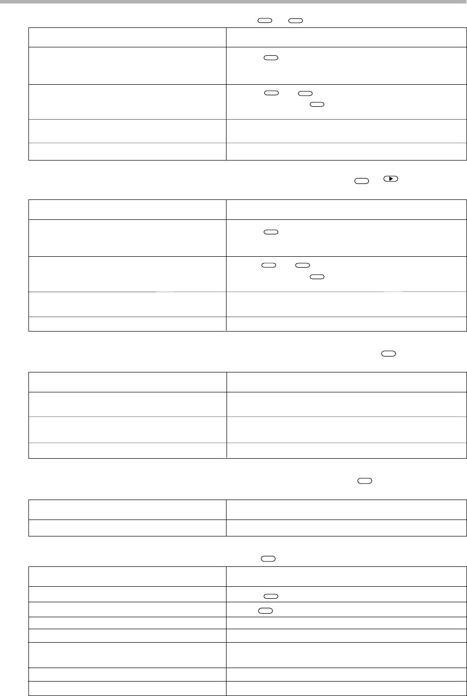
■ The program is not advanced by pressing
PROG
+
DISP
in the basic display state
The controller is in the READY mode.
The controller is in the END mode.
The controller is in the constant-value opera-
tion mode.
Key lock is enabled.
Cause Remedy
■ The controller does not change to FAST mode by pressing
FUNC
+ in the basic
display state
The controller is in the READY mode.
The controller is in the END mode.
The controller is in the constant-value opera-
tion mode.
Key lock is enabled.
Cause Remedy
Press
RUN/HOLD
to set the controller to the RUN mode. (The
controller can be reset in case of external switch input
or communications even in the READY mode.)
Press
PROG
+
RUN/HOLD
to set the controller to the READY
mode, and press
RUN/HOLD
again to set the controller to the
RUN mode.
Set constant-value operation data M .O D E setting to 0.
Set variable parameter
L O C setting to 0 to 2.
■ The controller does not change to MANUAL mode by pressing
A/M
in the basic
display state
ON-OFF control is being carried out by 0D
and 6D outputs.
3-position-proportional control is selected by
3D output.
Key lock is enabled.
Cause Remedy
Set PID set
P setting in use to other than 0.0 and switch
to PID control from ON-OFF control.
Set setup data C 4 5 setting to 0 and switch to PID
control from 3-position-proportional control.
Set variable parameter
L O C setting to 0 to 2.
■ The controller does not change to AUTO mode by pressing
A/M
in the basic dis-
play state
Key lock is enabled. Set variable parameter L O C setting to 0 to 2.
Cause Remedy
The controller is in the READY mode.
The controller is in the MANUAL mode.
Input 1 over-range
Controller set not to execute AT.
The controller is set to programmer functions
by 5G output.
This is a heat/cool model.
Key lock is enabled.
Cause Remedy
Press
RUN/HOLD
to set the controller to the RUN mode.
Press
A/M
to set the controller to the AUTO mode.
Correctly wire input 1 to correct input state.
Set variable parameter
A T setting to other than 0.
Set setup data
C 1 8 setting to 0.
AT cannot be executed by 3D and 5K outputs.
Set variable parameter L O C setting to 0 to 2.
■ Auto-tuning (AT) is not started by pressing
AT
in the basic display state